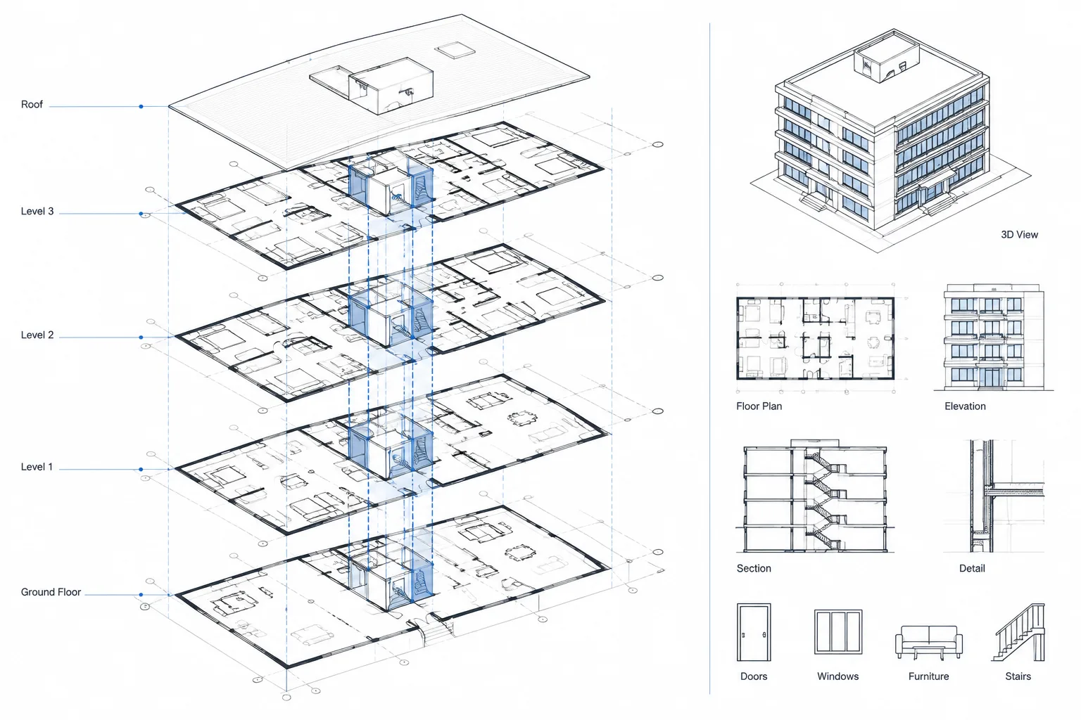
Organizing multistory architectural CAD files is a production decision, not merely a filing preference. The chosen structure determines how easily a team can compare levels, assign editing responsibility, exchange backgrounds, manage external references, and trace information back to an authoritative source.
This guide compares separate floor DWGs, combined floor-plan models, and hybrid reference assemblies. It also explains the coordination controls that matter regardless of method, including common origins, reference hierarchy, annotation ownership, sheet separation, and cross-floor review.
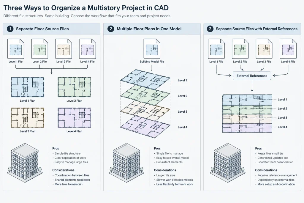
A multistory building can be organized in CAD several ways. Each floor may have its own DWG file, all floors may be drawn together in one model, or separate floor files may feed a composite coordination drawing. The geometry can look identical on a plotted plan, but the file structure strongly affects editing, external references, consultant exchange, sheet production, and quality control.
There is no universal arrangement for every project. The right choice depends on project size, team responsibilities, repeated floor plates, deliverable requirements, and the way backgrounds are exchanged. The important step is to choose a structure deliberately and document it before production drawings multiply.
The three common multistory CAD structures
One floor per DWG file
In a floor-by-floor structure, each building level is maintained in a separate model file. A typical project might have individual files for the ground floor, upper floors, roof, and other plan-based information. Those files are then referenced into sheet drawings or coordination files.
This approach creates clear ownership boundaries. A team member can work on one level without opening every floor, and a consultant can receive only the backgrounds relevant to a particular scope. It also limits the effect of file corruption or accidental edits because the entire building is not contained in one model.
The main coordination risk is inconsistency between files. Grids, shafts, exterior walls, stairs, and other vertically related elements may drift if users copy geometry instead of referencing a controlled source. Reliable origins and disciplined xref management are therefore essential.
Multiple floors in one DWG file
Another approach is to place several floor plans in a single model-space drawing, usually arranged side by side. This can be convenient during early design because users can compare levels, copy related geometry, and revise several plans without switching files.
The method can become difficult as the project grows. Layer lists, annotations, plan-specific symbols, and revision work may become crowded. It is also easier to select or move geometry belonging to the wrong floor. If consultants need separate backgrounds, the combined model may require additional preparation before every exchange.
Side-by-side plans should not be confused with floors drawn at different CAD elevations. Artificially separating plans along the Z axis often complicates otherwise two-dimensional architectural work. Unless the project has a specific three-dimensional coordination method, dependable plan alignment is usually easier when floor backgrounds share a consistent horizontal coordinate system.
A hybrid source-and-composite structure
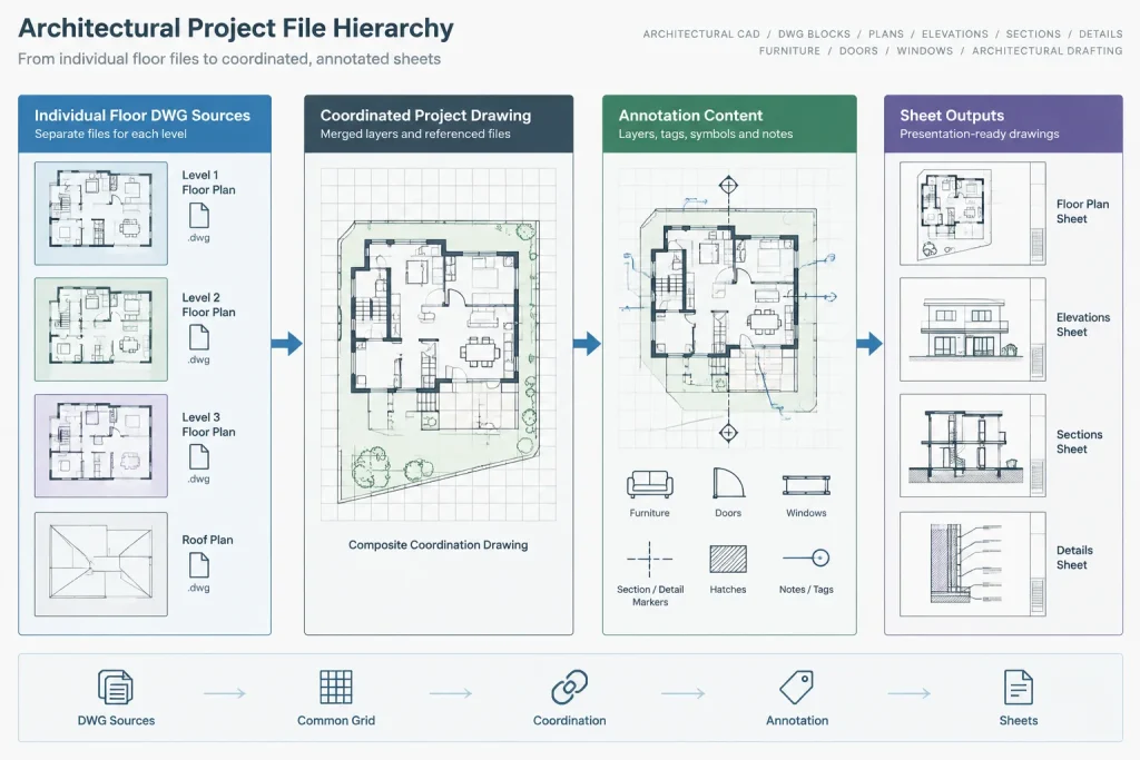
A hybrid workflow keeps each floor in a separate source DWG while assembling selected levels in one or more coordination files through external references. The source files remain the editable records. The composite file is used to compare floors, review vertical relationships, create diagrammatic views, or provide a convenient project overview.
This structure combines controlled floor ownership with easy cross-level checking. It does require users to understand which file contains editable source geometry and which file is only an assembly. Clear file naming and xref overlays help prevent circular references and accidental editing in the wrong location.
Comparison of file organization methods
| Consideration | One floor per file | Multiple floors in one file | Hybrid structure |
|---|---|---|---|
| Concurrent team editing | Usually easier to divide by level | More likely to create editing conflicts | Flexible when source ownership is clear |
| Consultant background exchange | Simple to issue selected levels | May require isolating or exporting content | Source floors can be issued individually |
| Cross-floor comparison | Requires references or separate open files | Convenient within the combined model | Convenient in a dedicated composite file |
| File complexity | Distributed across several files | Concentrated in one file | Distributed, with added reference management |
| Risk of geometry drift | Higher if shared elements are copied | Lower for nearby geometry, but accidental edits remain possible | Lower when common references are controlled |
| Sheet production | Works well with floor-specific sheets | Requires carefully managed views and layers | Sheets can reference the appropriate source or assembly |
Establish a common project origin
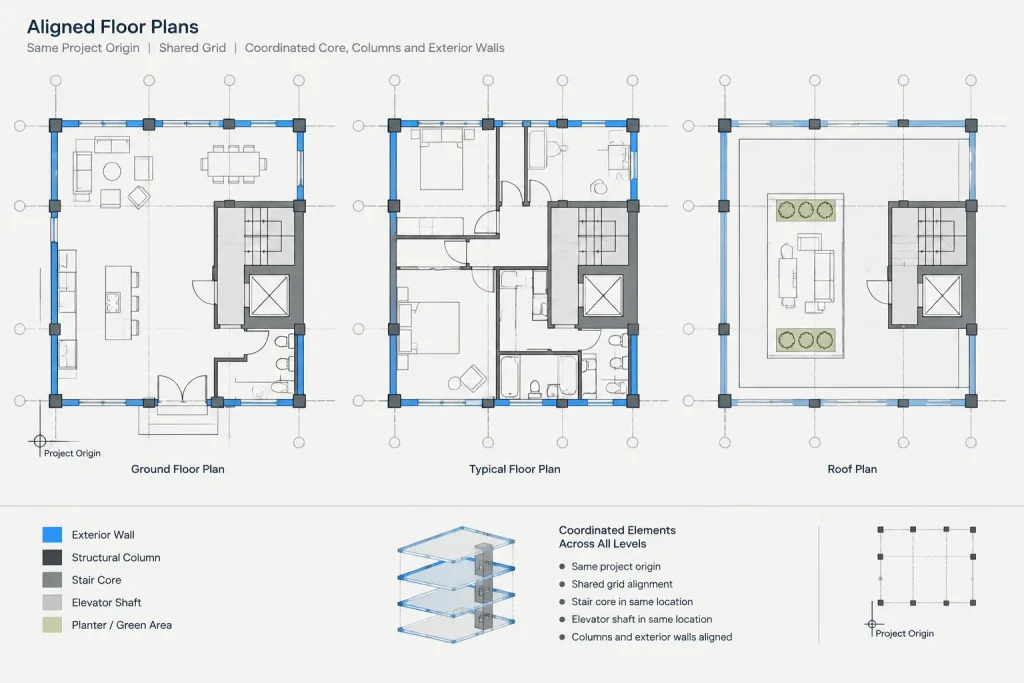
Every floor file should use the same agreed project origin and orientation. A grid intersection, survey control relationship, or another documented project reference can provide the basis, depending on the project workflow. The key is consistency rather than the visual convenience of placing each plan near the drawing origin independently.
A reliable origin allows floor files to be attached without manual movement or rotation. Columns, cores, stairs, shafts, facade lines, and structural grids can then be compared directly. If a floor must be repositioned every time it is referenced, the file structure is already introducing avoidable risk.
Include an origin check in background exchanges. A drafter can attach the new file into a controlled coordination drawing and compare known reference points before accepting it for production.
Control geometry shared by multiple floors
Repeated information should have an identified source. Column grids, primary cores, typical structural elements, and recurring exterior geometry are common examples. Copying this information into every floor file may be fast initially, but each copy can become an independent version.
Possible control methods include:
- Maintaining common grid information in a dedicated reference file.
- Referencing a typical floor only where repetition is genuine and clearly documented.
- Using a composite drawing to compare shafts, stairs, and facade control lines.
- Assigning responsibility for shared geometry instead of allowing several files to redefine it.
- Recording approved exceptions where one level intentionally differs from the others.
Do not force unique floors into a typical-floor system simply because they appear similar. A repeated plan should only be reused when the project team can manage its exceptions without obscuring real differences.
Separate model geometry from plan-specific annotation
Multistory file organization also affects room tags, door tags, dimensions, notes, and callouts. Annotation that belongs to one floor should not become visible on unrelated levels. This is especially important when a shared model is used for several plan types.
Choose an annotation location that matches the project’s established production method. Some teams keep plan annotation with the source floor, while others place sheet-specific notes and dimensions in dedicated sheet or annotation files. Either approach can work if users know where authoritative information lives.
Avoid maintaining duplicate editable annotations for the same condition. If a room number, opening tag, or reference changes, the team should not have to discover and correct several independent copies.
Plan the xref relationships before building the file tree
A simple reference hierarchy is easier to troubleshoot than a deeply nested chain. Floor source files can reference controlled common backgrounds, while sheet files reference the required floor and annotation content. Composite coordination files can bring together multiple floors without becoming sources for ordinary plan sheets.
Overlay references are often useful when a nested background should not continue into another host drawing. Attachments may be appropriate when downstream drawings need the nested content. The project team should make that choice consistently rather than changing reference types only to solve temporary visibility problems.
Keep xref names recognizable, use a documented relative-path strategy when files must move together, and avoid circular references. A coordination file should not be referenced back into one of the floor files it already contains.
Use sheets as outputs, not geometry storage shortcuts
A sheet should present the required view at the intended plot scale; it should not become the only location where essential building geometry exists. If walls, doors, or other model elements are drawn directly over a viewport in paper space, later revisions and background exports can become incomplete.
Floor source geometry should remain available for reuse in plans, elevations, sections, and consultant backgrounds. Paper space is better reserved for sheet composition and any annotation intentionally managed at the sheet level.
A practical setup workflow
-
List the required plan sources. Identify building levels, roof plans, shared grids, existing-condition backgrounds, and other reusable plan geometry.
-
Choose the ownership model. Decide whether floors will be maintained separately, combined, or managed through a hybrid structure.
-
Define the origin and orientation. Test the proposed control points by referencing sample floor files together.
-
Create the file naming pattern. Names should distinguish source models, annotation files, coordination assemblies, and sheets without relying on folder location alone.
-
Define the xref hierarchy. Record which files may reference each other and whether nested references should pass through to hosts.
-
Test a representative sheet. Produce a plan sheet, reload its references, and verify layer visibility, annotation, plotting, and reference paths.
-
Run a cross-floor review. Overlay relevant levels and inspect grids, vertical circulation, shafts, openings, exterior alignment, and other continuous elements.
Quality-control checks for multistory files
- Confirm that every floor uses the approved origin and orientation.
- Check that xrefs load without manual repositioning.
- Verify that shared grids and control geometry come from an identified source.
- Look for copied elements that have diverged between levels.
- Review stairs, elevators, shafts, chases, and floor openings across adjacent floors.
- Confirm that plan-specific annotation appears only where intended.
- Check that sheet viewports reference current source files rather than outdated copies.
- Remove or clearly label temporary comparison geometry before issue.
- Verify that transmitted files include the required references and do not depend on unshared local paths.
Choosing the most suitable method
Separate floor files are generally effective when a project has many contributors, frequent consultant exchanges, or clearly divided level responsibilities. A combined model may remain practical for a small project with limited documentation and one primary editor. A hybrid structure is useful when the team needs both distributed production and regular cross-floor comparison.
The strongest multistory CAD file organization is not necessarily the most elaborate. It is the arrangement that keeps source geometry identifiable, preserves a common coordinate system, supports predictable sheet output, and makes vertical inconsistencies easy to detect. Establish those rules early, test them with real project files, and revise the structure before it becomes expensive to change.
Recognizing when the file structure needs to change
A CAD structure that worked during early design may become inefficient when additional contributors, consultant backgrounds, annotations, or sheets are introduced. The warning sign is not simply a large drawing. It is uncertainty about where geometry should be edited and which file represents the current source.
Common symptoms include repeated manual alignment, duplicated floor geometry, unexplained xref overrides, floor-specific information appearing on unrelated plans, and background packages that require extensive cleanup before transmission. Frequent editing conflicts can also indicate that too many responsibilities have been concentrated in one model.
Move from a combined model when ownership becomes unclear
A combined drawing may be divided into floor source files when separate editing responsibility or background exchange becomes more important. Before dividing it, establish a common origin, identify shared control geometry, and determine where annotation will remain. Extracting visible plan areas without resolving those relationships can preserve the original coordination problems in a different file arrangement.
Add a composite file when comparison is difficult
Separate floor files do not need to be merged merely to make cross-level review easier. A dedicated composite drawing can reference the authoritative sources while leaving ownership unchanged. This provides a review environment for vertical alignment without creating another editable copy of each plan.
Document authority as well as file names
A useful file map should explain more than the folder structure. It should identify which drawings contain source geometry, which assemble references, which carry annotation, and which exist only for sheet output or temporary coordination. That distinction helps users avoid editing a convenient composite when the actual revision belongs in a floor source.
Questions to resolve before issuing backgrounds
- Authority: Which DWG is the editable source for each floor and each shared element?
- Coordinates: Can issued backgrounds be referenced without manual movement or rotation?
- Dependencies: Which external references are required for the recipient to see the intended background?
- Annotation: Is the recipient receiving model geometry, plan annotation, or both?
- Visibility: Are temporary comparison layers, working notes, and unrelated levels excluded or clearly identified?
- Revision control: Can the team distinguish the current source from superseded exports and detached copies?
The selected organization method should remain understandable to someone who did not create it. Clear authority, predictable references, and repeatable checking are more valuable than a complex structure that depends on personal knowledge.
Frequently asked questions
Should every building floor have a separate DWG?
Not necessarily. Separate files are useful when levels have distinct ownership, require individual consultant backgrounds, or need independent issue control. A combined file may be manageable when the project and editing team are limited. The decision should follow the production workflow rather than a universal rule.
What is the main advantage of a hybrid CAD structure?
A hybrid structure preserves separate authoritative floor files while providing a composite drawing for cross-floor review. It supports comparison without requiring the team to maintain duplicate editable floor geometry.
Should floor plans be separated by CAD elevation?
Only when that arrangement is part of a deliberate coordination method. Artificial vertical separation can complicate ordinary plan referencing and alignment. For plan-based production, a consistent horizontal coordinate system is often easier to review and exchange.
Where should dimensions and tags be stored?
They should be stored according to a documented annotation strategy. Some workflows keep floor-specific annotation with the floor source, while others use separate annotation or sheet files. The important requirement is to avoid competing editable copies of the same information.
Can a coordination composite be used as a sheet background?
It can be used when that role is intentional and its reference behavior is controlled. However, a review assembly should not automatically become the production source. Teams should distinguish coordination files from authoritative floor models and sheet outputs.
How can floors be checked for alignment?
Reference the relevant floor sources into a controlled comparison drawing and inspect agreed control points, grids, cores, stairs, shafts, openings, and exterior lines. Misalignment should be corrected in the authoritative source rather than concealed by moving an xref in a downstream file.