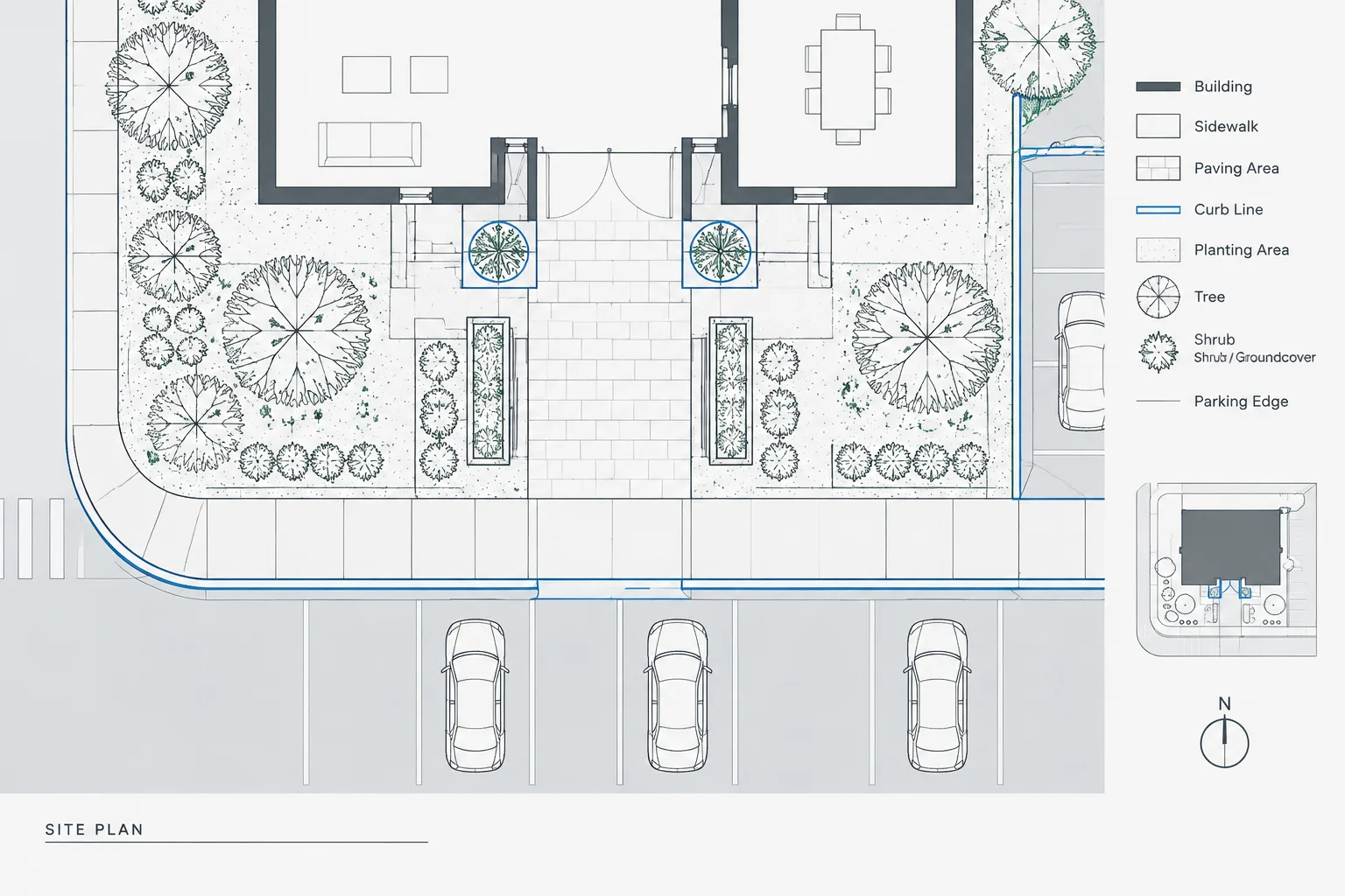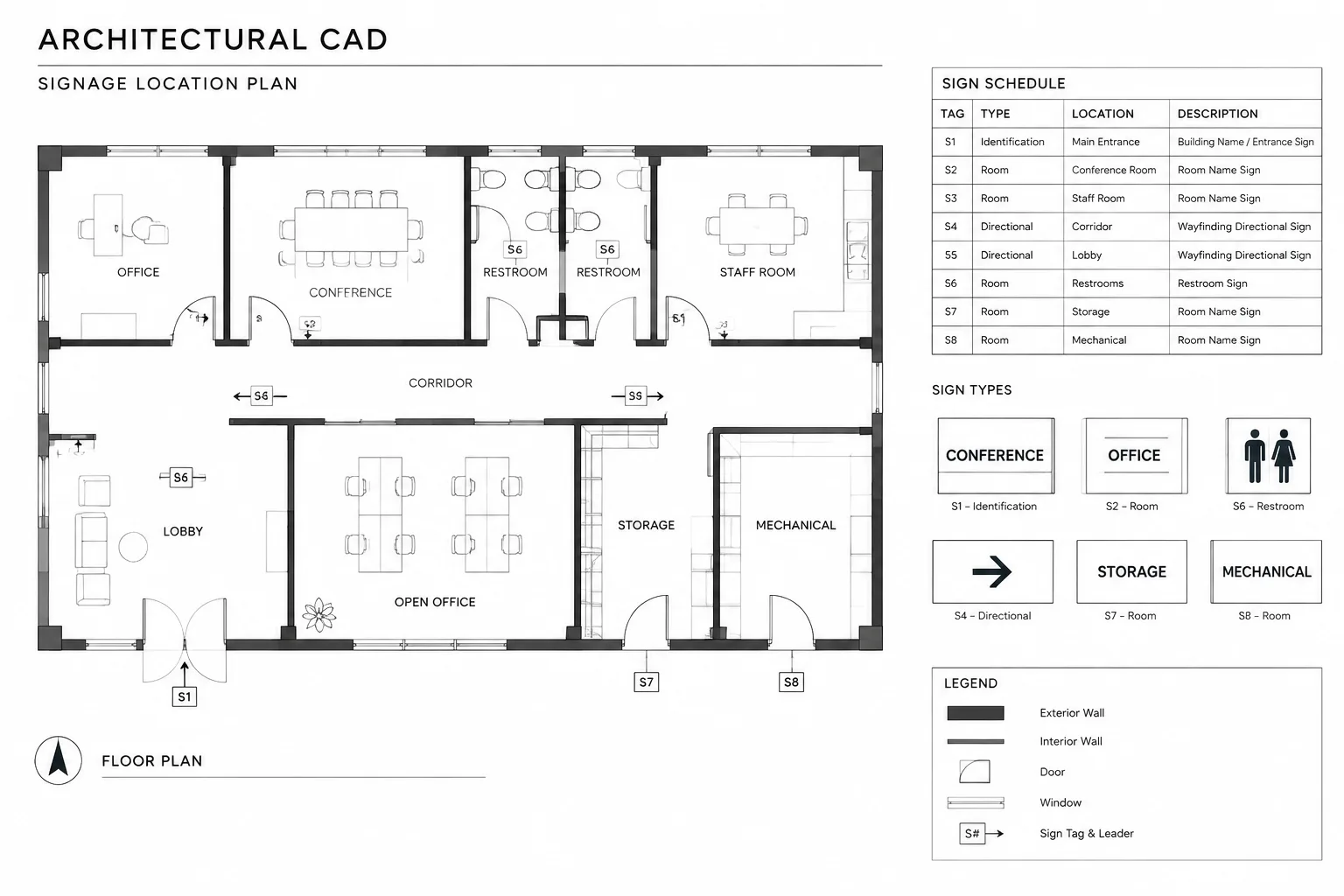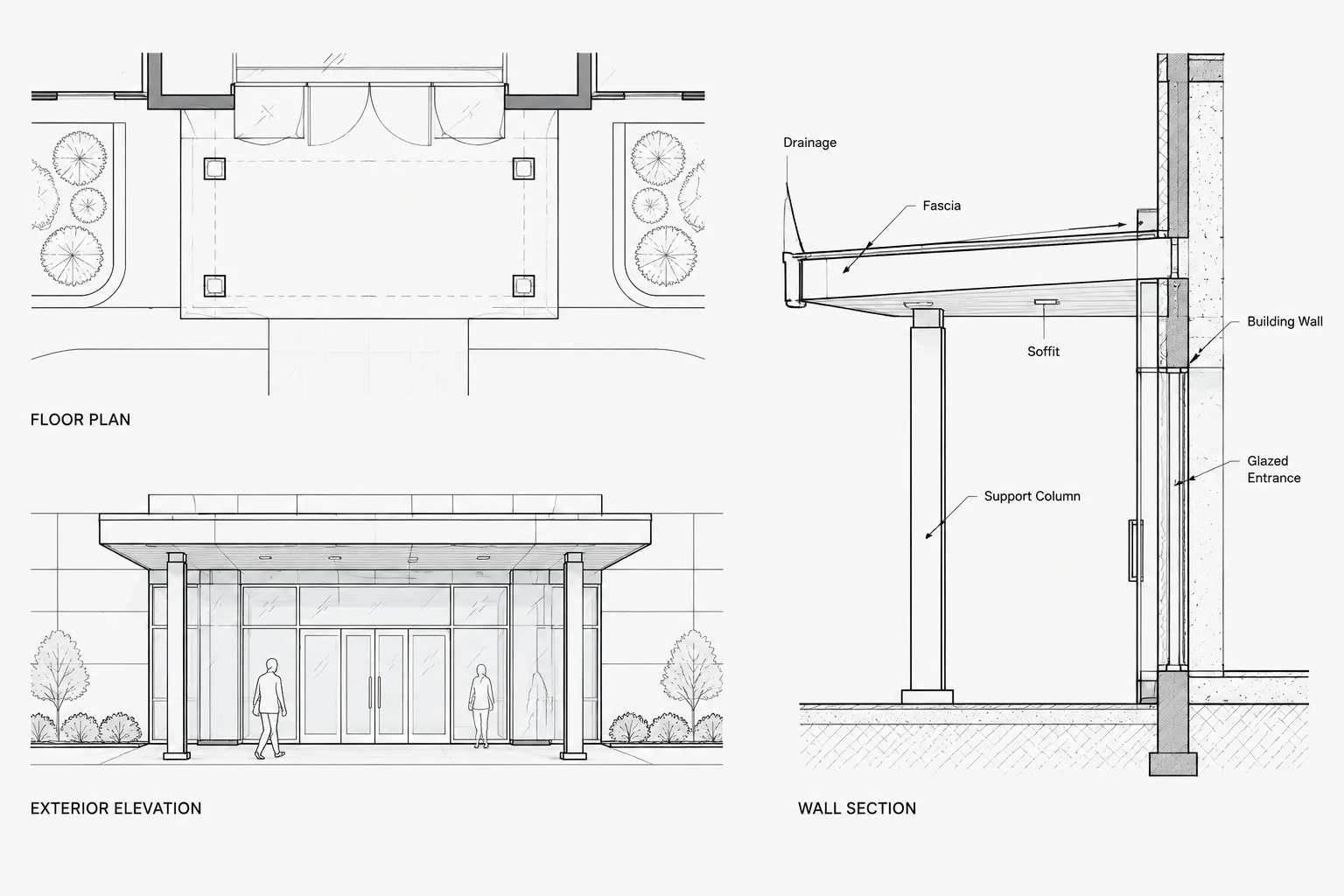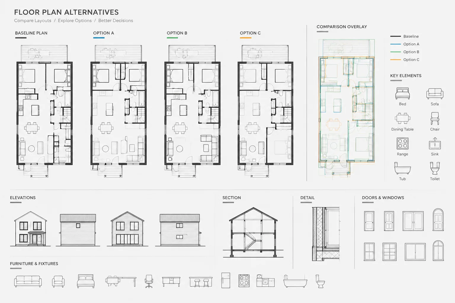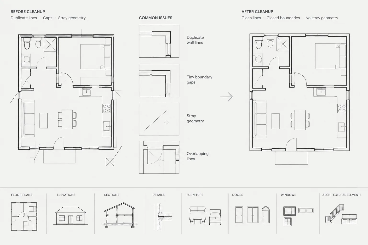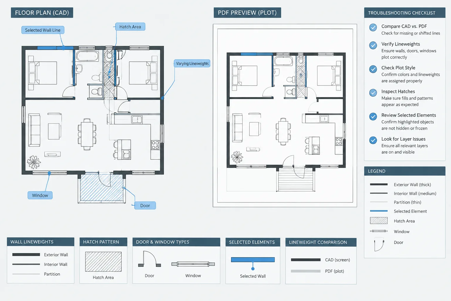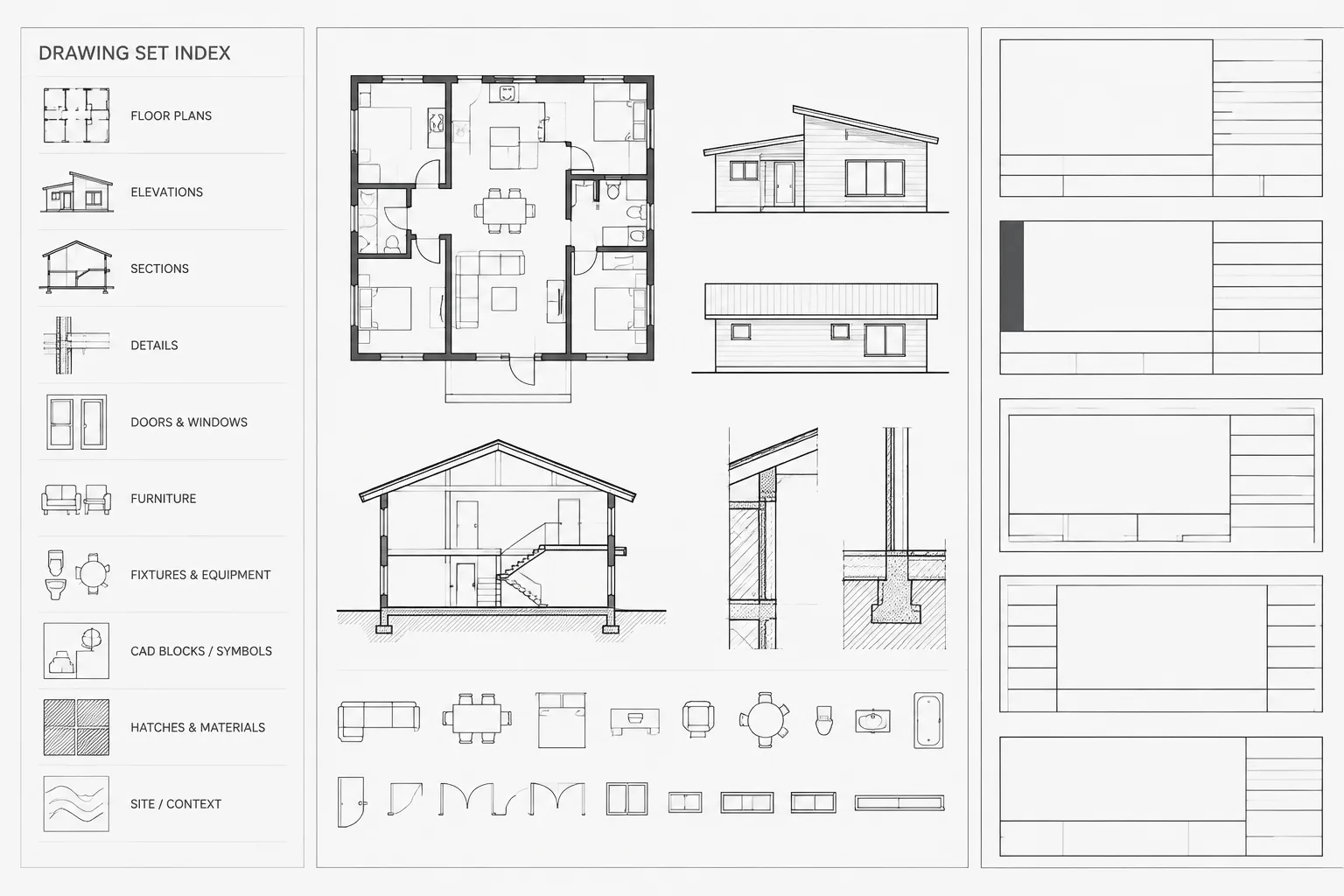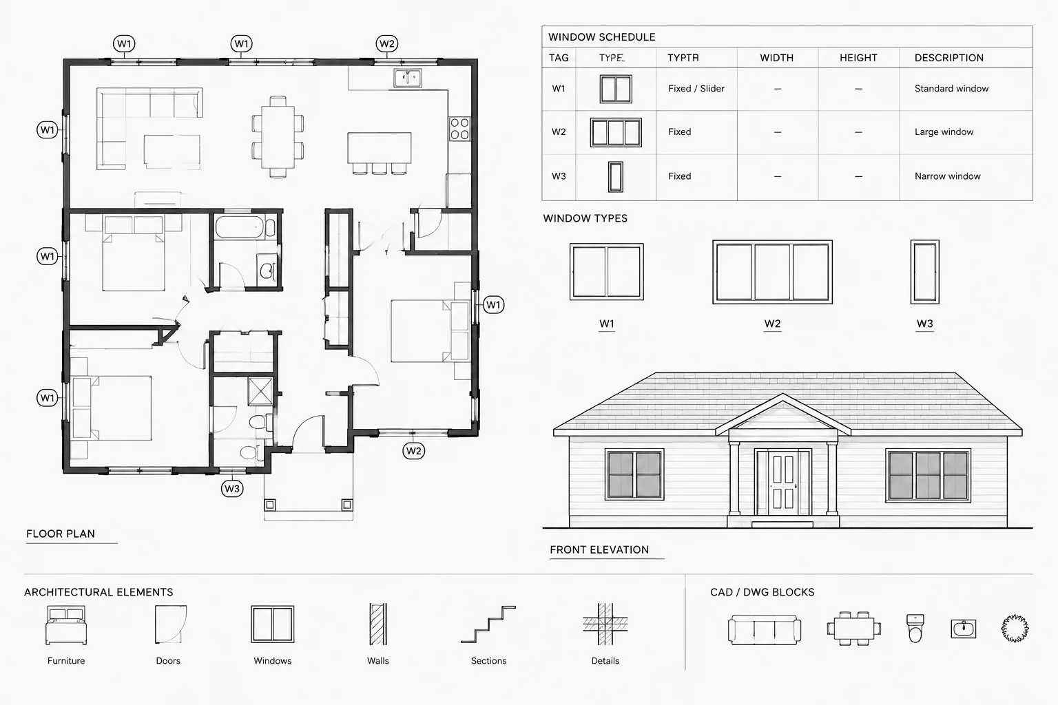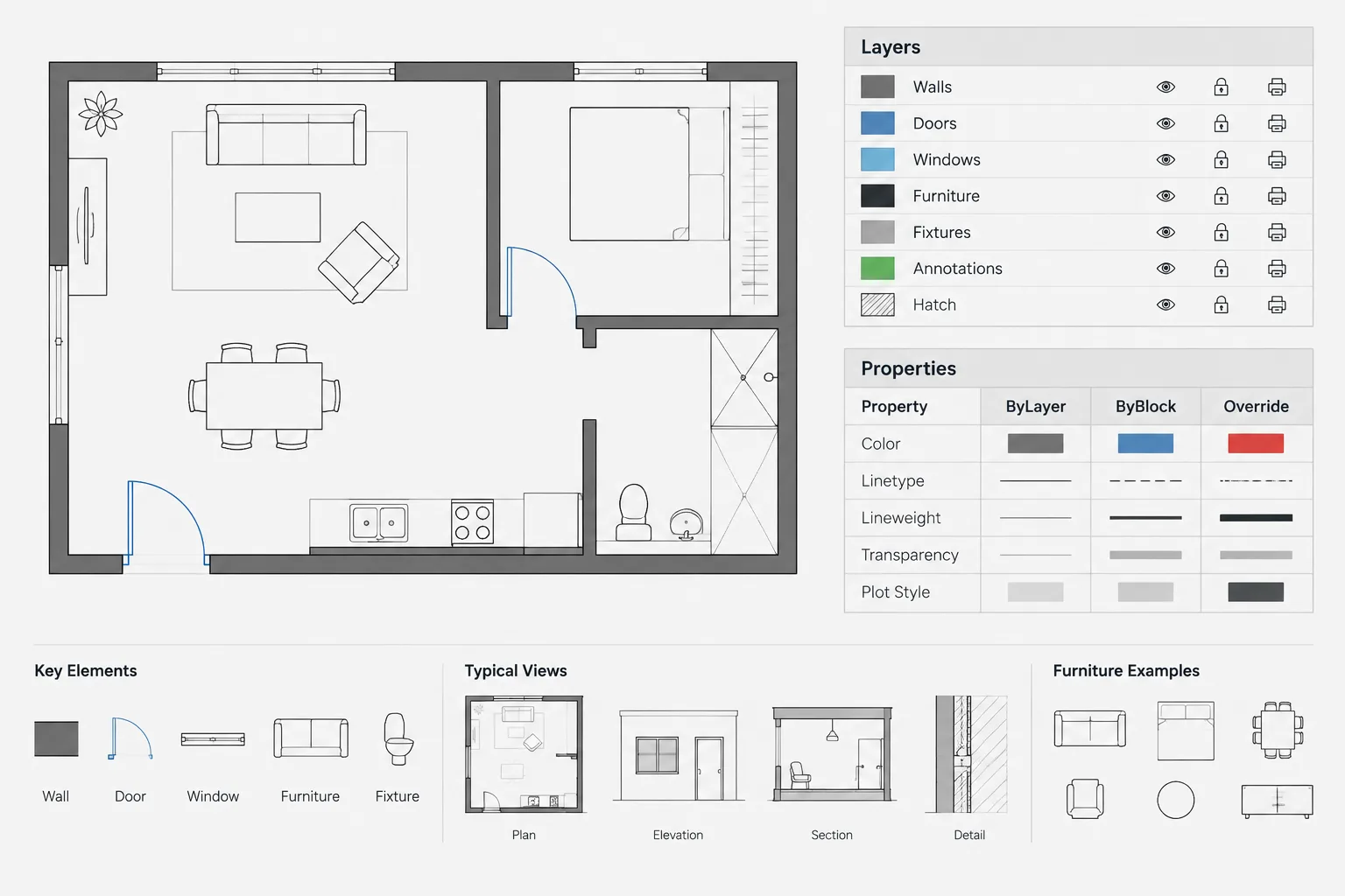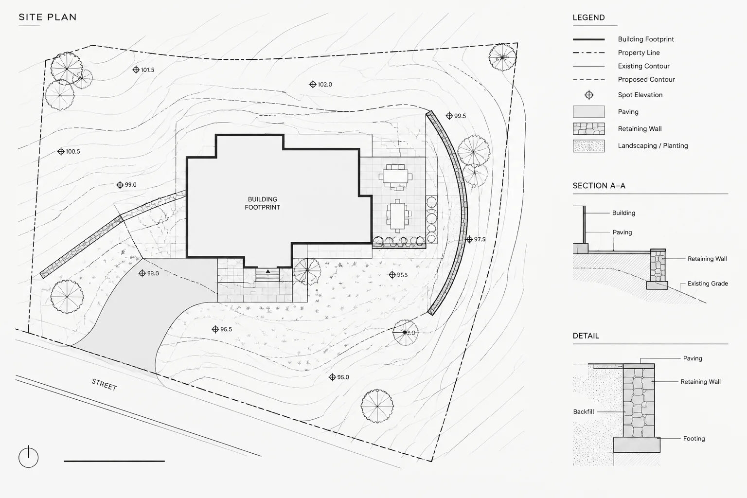
Drafting site grading contours in architectural CAD is primarily a coordination task. The architectural drawing must communicate how the building meets the terrain while preserving the authority, location, and status of survey and civil information.
This guide explains how to manage contour references, distinguish existing and proposed conditions, review building-edge relationships, coordinate spot elevations, and prepare legible grading graphics for plotted site plans.
Site grading information connects the building to the surrounding ground. On an architectural site plan, contours, spot elevations, drainage paths, retaining elements, entrances, and exterior surfaces must work together without making the drawing difficult to read.
Architects commonly receive grading data from a surveyor or civil engineer rather than create it independently. The architectural CAD task is therefore often one of careful reference management, graphic presentation, and coordination. A clean workflow preserves the authority of the source information while making the relevant relationships understandable in the architectural drawing set.
Understand what contour lines represent
A contour line connects points at the same elevation. Closely spaced contours indicate a more rapid change in ground elevation, while wider spacing indicates a more gradual change. The direction of drainage cannot be determined from spacing alone; it must be interpreted together with contour values, spot elevations, high and low points, and any verified drainage information.
Architectural drawings may need to distinguish between two basic contour conditions:
- Existing contours describe surveyed ground conditions before proposed construction.
- Proposed contours describe an intended finished grading configuration developed by the responsible design discipline.
Never assume that an unlabeled contour is existing or proposed. Confirm its status from the source file, drawing legend, layer names, and project documentation.
Begin with an authoritative site reference
Use the current survey or civil base as the controlling source. Whenever possible, attach it as an external reference rather than copying its geometry into the architectural model. Referencing helps preserve coordinates, supports updates, and reduces the risk of editing consultant information accidentally.
Before drafting around the reference, check:
- The drawing units and coordinate system used by the source file
- The project origin, rotation, and relationship to the architectural plan
- Whether elevations use the project datum, a survey datum, or another reference
- Which layers contain existing contours, proposed contours, labels, spot elevations, and breaklines
- Whether the file is current and suitable for the issue being prepared
Do not move, rotate, or scale a survey reference merely to make it appear aligned. If alignment is incorrect, investigate the coordinate setup and consult the responsible team member. An apparent graphic mismatch may indicate a larger coordination problem.
Separate source data from architectural presentation
The survey or civil file may contain more information than an architectural site plan needs. Rather than deleting source objects, control their visibility through reference layers, layer states, viewport settings, or a dedicated presentation file.
A practical layer structure should distinguish the following information:
| Information | Recommended graphic role | Coordination concern |
|---|---|---|
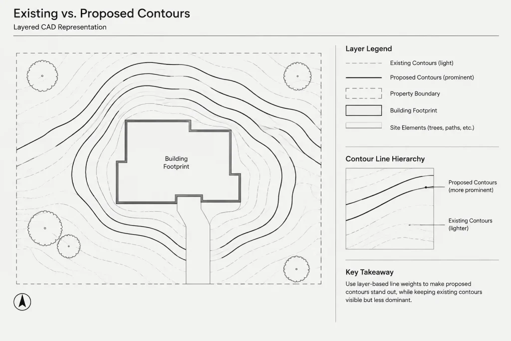
| Existing contours | Light background context | Must remain identifiable as surveyed information |
| Proposed contours | More prominent than existing contours | Must match the current grading design |
| Contour labels | Readable but subordinate to major site notes | Values must come from verified source data |
| Spot elevations | Emphasized at important transition points | Datum and surface condition must be clear |
| Breaklines and grade limits | Distinct from contour lines | Should not be mistaken for property or paving lines |
| Drainage features | Clearly identifiable where relevant | Location and function require discipline coordination |
If the architectural team must create simplified presentation contours, retain the original reference beneath them and identify the simplified linework appropriately. Do not redraw approximate contours and present them as surveyed or engineered information.
Draft contour geometry carefully
Contour lines are commonly represented with continuous polylines or other connected curve geometry. The exact method should follow the office workflow and the quality of the source data. The goal is continuous, editable linework without unnecessary vertices, gaps, or overlapping fragments.
Preserve continuity
A contour should continue logically until it exits the view, closes around a landform, or is interrupted by a feature that changes the surface. Avoid arbitrary gaps created only to reduce visual density. Where labels interrupt a line, apply a consistent masking or break convention that does not suggest the contour has physically ended.
Avoid excessive smoothing
Survey-derived contours may look irregular because they reflect measured terrain and the way the source surface was generated. Aggressive smoothing can move the apparent grade, conceal abrupt transitions, or create false low points. Simplify only when the purpose and acceptable tolerance have been established by the responsible project team.
Check crossings and overlaps
Contours representing different elevations should not cross on an ordinary continuous ground surface. A crossing may indicate duplicate data, incorrect elevation assignment, a drafting error, or a special physical condition requiring clearer representation. Inspect intersections rather than hiding them graphically.
Coordinate the building edge with grade
The most important architectural review occurs where the building meets the site. Compare grading information with floor levels, entrances, exterior doors, foundation walls, areaways, ramps, stairs, terraces, loading areas, and service zones.
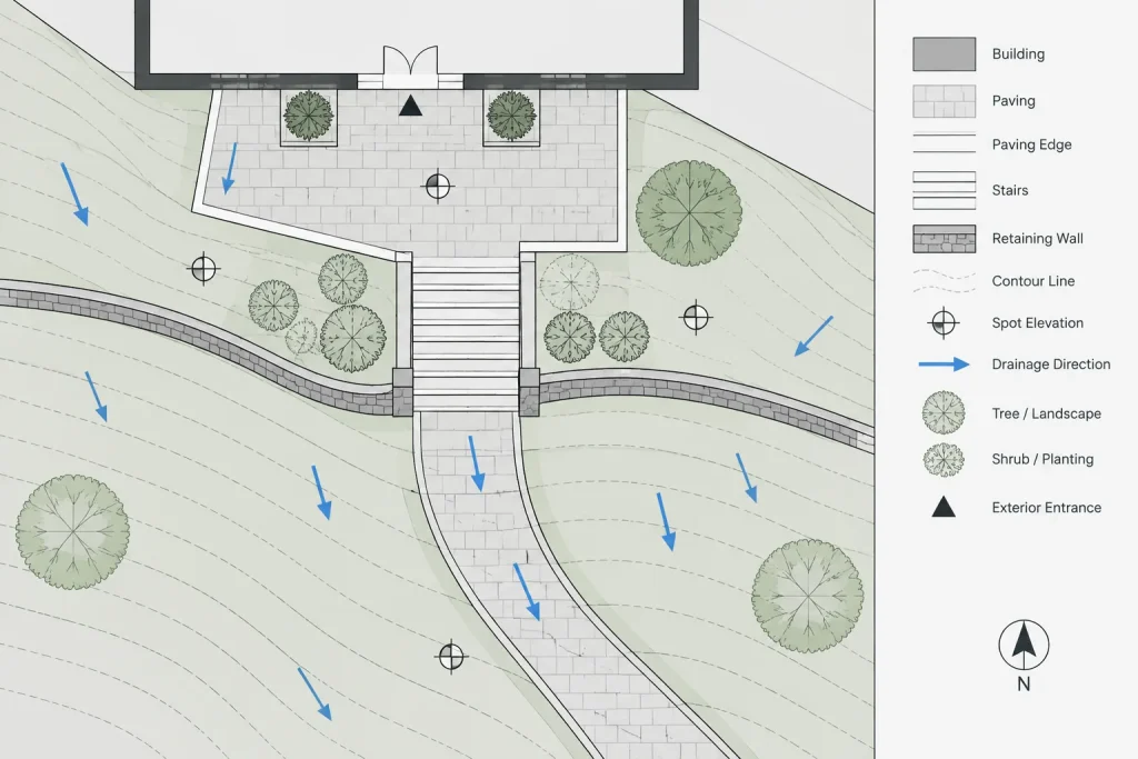
Review each significant building perimeter condition for the following:
- Which contour reaches or approaches the wall
- Whether the nearby spot elevations agree with the contour pattern
- How exterior paving connects to door thresholds and landings
- Where the ground changes abruptly or requires a retaining condition
- Whether plan information agrees with building elevations and wall sections
- Whether downspouts, drains, swales, or other drainage elements appear in coordinated locations
Do not infer code compliance, drainage performance, or waterproofing adequacy from contour graphics alone. Those conclusions require verified design criteria and coordination with the appropriate disciplines.
Use spot elevations to clarify critical locations
Contours describe the broader landform, but spot elevations clarify exact points selected by the design team. They are especially useful at entrances, paving corners, tops and bottoms of exterior steps, retaining transitions, drainage structures, and other locations where a contour alone may be ambiguous.
A spot elevation symbol should make clear what point it refers to. Place the marker at the measured or designed location, keep the text legible, and avoid leaders that cross unrelated site features. If the notation distinguishes between surfaces or vertical conditions, use the project legend and discipline conventions rather than inventing abbreviations.
All displayed values must come from a verified source. Architectural drafters should not interpolate or round elevations merely to fill a graphic gap unless that work is explicitly part of an authorized design process.
Label contours without cluttering the plan
Contour labels should be frequent enough for a reader to understand the terrain but not so frequent that they dominate the drawing. Position them along relatively clear portions of the line and orient them consistently for sheet reading.
Before plotting, verify that:
- Labels are associated with the correct contour
- Existing and proposed labels cannot be confused
- Text is not hidden beneath hatches, masks, or referenced objects
- Contour values use the same elevation basis as related spot elevations
- Labels remain readable at the intended viewport scale
When a contour passes beneath a building footprint, dense planting, or a large annotation area, use view controls intentionally. Avoid random trimming that makes future source updates difficult to reconcile.
Coordinate grading with other site-plan information
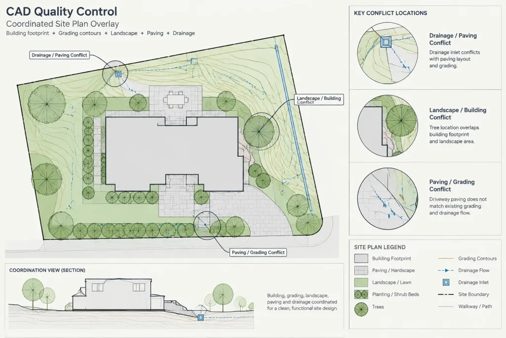
Grading cannot be reviewed in isolation. Overlay or compare it with property information, paving, landscape plans, utilities, drainage elements, accessible routes, and structural foundation information as appropriate to the project.
Common conflicts include proposed contours passing through fixed structures, spot elevations that disagree across drawings, retaining walls shown on only one discipline’s plan, and exterior steps that do not correspond with the documented level change. Another frequent issue is using an outdated grading reference after the building footprint or entrance configuration has changed.
Record questions through the project’s established coordination process. Do not quietly modify consultant contours in the architectural file to make a conflict disappear.
Prepare grading graphics for plotted sheets
A grading plan can look clear in model space and still become unreadable when plotted. Test the actual sheet viewport early. Existing information should normally recede, while proposed work and essential coordination points remain visible.
Use lineweight, linetype, tone, and annotation hierarchy together. Do not rely entirely on color because the final output may be monochrome or reproduced at reduced quality. Contours should remain distinguishable from property lines, utility lines, paving joints, and landscape edges.
If the site is complex, consider separate views for existing conditions, proposed grading, or focused building-interface areas. A crowded combined plan is not automatically more informative.
Final grading coordination checklist
- Confirm that the survey or civil reference is current.
- Verify units, coordinates, rotation, and elevation datum.
- Distinguish existing contours from proposed contours.
- Check contour continuity, labels, and unexpected crossings.
- Compare contours with verified spot elevations.
- Review entrances, paving, stairs, ramps, walls, and exterior level changes.
- Coordinate grading with sections, elevations, landscape, civil, and structural information.
- Confirm that architectural presentation edits do not alter source design data.
- Inspect lineweights and text at the intended sheet scale.
- Resolve or document discrepancies before issuing the drawing.
A reliable site grading drawing is not simply a collection of curved lines. It is a coordinated representation of how the building, exterior surfaces, and surrounding ground relate. By preserving authoritative source data, separating existing and proposed conditions, and checking critical interfaces, architectural CAD users can create clearer site plans without overstepping the responsibilities of the surveyor or civil engineer.
Manage grading revisions without losing data lineage
Grading information often changes as entrances, paving, retaining conditions, drainage features, and building limits are coordinated. Each update should remain traceable to its source rather than being absorbed into undocumented architectural linework.
When a revised survey or civil file is received, compare it with the currently referenced file before replacing or reloading it. Review the areas that affect the architectural design instead of relying only on a visual check of the entire site.
- Confirm the file identity, issue status, and responsible discipline.
- Check whether the origin, coordinates, units, rotation, or elevation basis have changed.
- Compare grading near entrances, exterior circulation, retaining elements, and the building perimeter.
- Look for revised spot elevations, contour limits, breaklines, drainage features, and surface boundaries.
- Record unresolved differences through the established project coordination process.
If architectural annotations depend on consultant geometry, verify them after every relevant reference update. A label, leader, mask, or enlarged detail may remain visible even when the source feature it described has moved.
Separate graphic clarity from design authority
Lineweight changes, viewport controls, masking, and annotation placement can improve readability without changing the underlying grading design. Moving a contour, revising an elevation, or altering a drainage feature is different: those actions change technical information and require authorization from the responsible discipline.
A useful review question is whether an edit changes only how information is displayed or changes what the information means. Keep presentation adjustments reversible, preserve the referenced source, and avoid creating architectural copies that can become detached from later consultant revisions.
Document discrepancies rather than concealing them
When contours, spot elevations, sections, and architectural levels do not agree, retain enough information to show where the conflict occurs. A concise coordination note should identify the location, the drawings or files being compared, and the decision needed. This makes the issue easier for the responsible team members to evaluate and prevents an unverified graphic correction from being mistaken for an approved grading change.
Frequently asked questions about grading contours in CAD
Should architects redraw contours received from a surveyor or civil engineer?
Not as a routine replacement for the source data. Referencing the authoritative file generally provides better update control and reduces accidental modification. Simplified presentation linework should remain identifiable as a graphic treatment rather than surveyed or engineered information.
How can existing and proposed contours be distinguished?
Use the project layer structure, legend, linetype, tone, and lineweight hierarchy. The distinction should remain clear when plotted and should not depend only on screen color.
Can drainage direction be determined from contour spacing?
No. Spacing indicates how gradually or rapidly elevation changes, but drainage interpretation also requires contour values, spot elevations, high and low points, breaklines, and verified drainage information.
What should be checked when contours appear misaligned with the building?
Review units, coordinate settings, project origin, rotation, reference insertion, and the current status of both files. Do not move or scale the site reference merely to make the graphics appear aligned.
Why might a contour cross another contour?
On an ordinary continuous ground surface, the crossing may indicate duplicate geometry, an incorrect elevation assignment, source-file problems, or a drafting error. It may also represent a special physical condition that needs a clearer drawing convention and discipline review.
When are spot elevations more useful than contours?
Spot elevations help clarify selected points where broader contour patterns are insufficient, such as entrances, paving transitions, exterior steps, retaining conditions, and drainage features. Their values and elevation basis must come from verified project information.
What should be rechecked after a grading reference is updated?
Recheck architectural labels, leaders, masks, enlarged views, entrance relationships, exterior circulation, wall interfaces, and related sections or elevations. Also confirm that layer and viewport controls still produce the intended plotted hierarchy.