A coordinated room finish plan is more than a collection of hatch patterns. It is a location-based drawing that connects material extents and transitions with room data, finish descriptions, elevations, and construction details. If those sources are not organized consistently, even a visually complete plan can contain conflicting or outdated instructions.
This guide explains a practical room finish plan CAD workflow, including background preparation, finish coding, boundary control, schedule coordination, drawing readability, and quality review. The goal is to create finish documents that remain understandable as rooms, doors, casework, and material selections change during design.
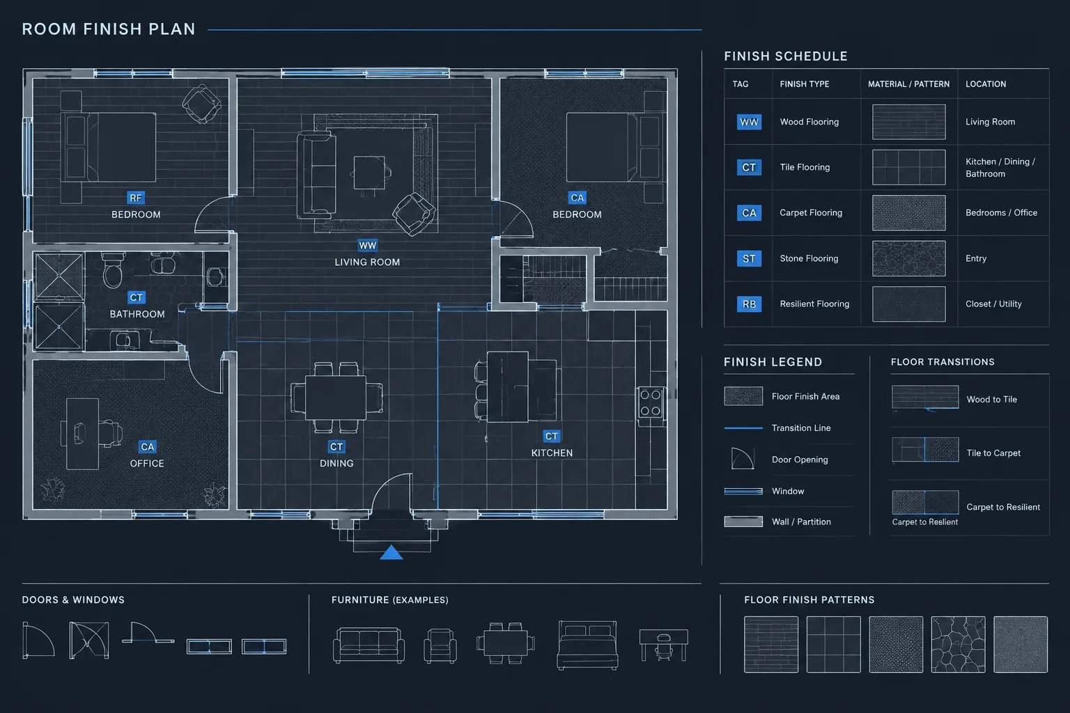
A room finish plan communicates where architectural finishes begin, end, and change within a project. It may identify flooring, base, wall finishes, ceiling finishes, transitions, patterns, and special conditions. The accompanying room finish schedule organizes related information by room. Used together, the plan and schedule provide a coordinated reference that is more useful than either document alone.
Finish drawings can become difficult to maintain when information is duplicated across plans, elevations, schedules, and notes. A reliable room finish plan CAD workflow therefore depends on clear information ownership: each finish requirement should have one primary source, while other views provide location, orientation, or construction context.
Define the purpose of the finish documents
Before drafting, decide what the finish plan must communicate. The answer depends on project scope, drawing scale, procurement process, and office standards. Some projects use a dedicated floor finish plan, while others combine several finish categories in one view. Complex interiors may require separate wall finish plans, ceiling finish information, interior elevations, or enlarged plans.
A typical finish-document package may include:
- A plan showing finish extents, boundaries, transitions, and directional patterns.
- Room tags or finish tags connecting locations to scheduled information.
- A room finish schedule listing finish designations by room and surface.
- A finish legend defining abbreviations and material codes.
- Interior elevations showing wall-specific changes that are unclear in plan.
- Details for thresholds, base transitions, trim, reveals, or material terminations.
- General notes covering recurring installation or coordination conditions.
Do not force every finish requirement into the plan. The plan should answer spatial questions, while schedules and details should carry organized descriptive information.
Start with a coordinated architectural background
Build the finish plan from the current architectural floor plan rather than creating an independent copy of the building geometry. An externally referenced background or another controlled project workflow helps keep walls, openings, room limits, and fixed elements aligned with the primary plan.
Review the background before adding finish graphics. Confirm that the rooms are enclosed correctly, door openings are current, built-in casework is represented, and floor openings or level changes are visible. Finish boundaries based on outdated partitions can remain visually plausible while being technically wrong.
Simplify background graphics where necessary. Finish information should be visually prominent, so furniture, equipment, dimensions, and unrelated annotation may need to be screened, frozen, or omitted in the finish view. Preserve enough context to identify rooms, circulation, doors, fixed fixtures, and significant construction edges.
Establish a finish identification system
Use short, consistent finish designations that connect drawings, schedules, specifications, and material submittals. A designation should identify a finish category without trying to contain the full product description. The detailed description can remain in the finish schedule, legend, or project specification.
A project may organize identifiers by material family, surface type, or another office convention. Whatever system is selected, avoid using the same code for unrelated materials. Also avoid changing identifiers simply because a drawing becomes crowded; graphical clarity should be solved through annotation placement, enlarged views, or keyed references.
Create a controlled list early and add new designations deliberately. Near-duplicate codes, inconsistent punctuation, and informal abbreviations are common sources of coordination errors.
Draw finish regions as intentional boundaries
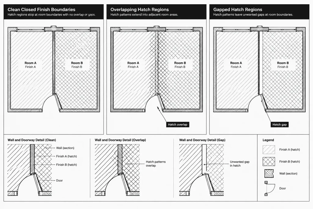
Finish regions should be based on closed, maintainable boundaries rather than loosely arranged hatch fragments. Determine where each material logically terminates: at a wall face, door centerline, threshold, casework edge, change in floor level, or a specifically documented transition.
Separate the boundary geometry from the visible hatch when practical. This makes it easier to edit an extent, audit overlaps, and replace a hatch without reconstructing the design boundary. Place finish outlines, hatches, transition lines, symbols, and tags on appropriate layers so each type of information can be controlled independently.
Resolve boundaries at openings
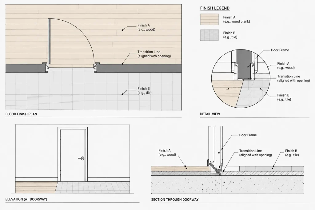
Doorways require deliberate decisions. A floor finish may continue through an opening, stop beneath the door, or meet another finish at a transition profile. Do not allow adjacent hatches to meet at an arbitrary location merely because that point is easy to draw. Coordinate the plan with the door frame, threshold condition, floor elevations, and associated detail.
Account for fixed construction
Clarify whether flooring extends beneath built-in casework, equipment, raised platforms, or permanent fixtures. The answer may affect quantities, sequencing, substrate preparation, and visible edges. If the condition cannot be understood from the finish plan, reference an elevation or detail rather than relying on an ambiguous hatch.
Use hatches without sacrificing readability
Hatches are useful for showing extent and direction, but they should not be treated as the sole material identifier. Similar patterns can become difficult to distinguish when printed, reduced, copied, or viewed in grayscale. Pair graphical patterns with finish tags or a clear legend.
Choose hatch density according to the plotted drawing, not only the model-space view. Dense patterns can obscure door swings and room tags, while patterns that are too open may disappear at the intended sheet scale. Test representative areas in a PDF or physical plot before applying the graphic system throughout the project.
Use hatch orientation when it communicates design intent, such as the direction of planks, linear tile, or patterned materials. If the starting point or alignment matters, show a control line, origin note, or dimensioned relationship. A rotated hatch by itself may not adequately define installation intent.
Coordinate room tags and localized finish tags
A room finish schedule can establish the default finishes for an entire room. Local finish tags can then identify exceptions, feature areas, borders, accent walls, or transitions. This reduces repeated annotation while preserving location-specific information.
Keep the distinction clear:
- Room information identifies the space and its scheduled default finishes.
- Finish tags identify a particular material region or surface.
- Transition tags identify a change between adjacent finish conditions.
- Detail references direct the reader to construction information.
Do not place multiple conflicting identifiers over the same area. When several finishes occur in a small room, use an enlarged plan or interior elevation instead of clustering leaders and tags into an unreadable group.
Build the room finish schedule around information ownership
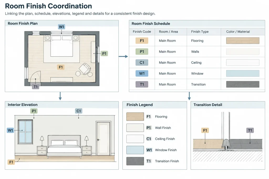
The schedule should be structured so each field has a clear purpose. A practical organization may include room identification, floor finish, base, wall finish, ceiling finish, and remarks. Actual columns should match the project’s scope and documentation strategy.
| Information type | Best primary location | Coordination concern |
|---|---|---|
| Default room finishes | Room finish schedule | Keep room names and numbers aligned with plans. |
| Material extent and direction | Finish plan | Check boundaries, openings, and pattern orientation. |
| Wall-specific finish changes | Interior elevation | Coordinate corners, heights, and adjacent surfaces. |
| Transition construction | Detail | Coordinate substrates, levels, and adjoining materials. |
| Full material description | Legend or specification | Use the same finish designation everywhere. |
Avoid repeating complete descriptions in several locations. If a material description changes, every manually duplicated instance becomes a potential discrepancy. Establish one authoritative description and use the finish code to connect other drawings to it.
Coordinate wall, floor, base, and ceiling conditions
Finish coordination extends beyond choosing materials. Review how surfaces meet one another and how those interfaces are documented.
- Check whether base finishes change when floor or wall finishes change.
- Review inside and outside corners where wall finishes terminate.
- Coordinate floor transitions with door frames and door swings.
- Confirm whether ceiling finish information belongs on the finish plan, reflected ceiling plan, or schedule.
- Check finish extents around casework, plumbing fixtures, columns, and recessed elements.
- Identify surfaces requiring elevations because plan graphics cannot show vertical limits.
- Coordinate changes in substrate or floor level with relevant sections and details.
Where drawings conflict, resolve the design rather than adding a general note intended to cover every uncertainty.
Apply a focused quality-control review
Finish-plan review should combine graphical checks with schedule comparison. A useful sequence is to inspect one room at a time and then review transitions between rooms.
- Confirm every scheduled room appears on the current plan.
- Check that room numbers and names match across plans and schedules.
- Look for unlabeled finish regions and finish codes not included in the legend.
- Inspect hatch boundaries for gaps, overlaps, and coverage beneath walls or fixed objects.
- Review every doorway and open connection between different floor finishes.
- Compare wall finish references with interior elevations.
- Verify that hatch direction agrees with documented layout intent.
- Check base conditions at finish changes and curved or irregular walls.
- Confirm detail references point to existing, relevant details.
- Plot the sheet at its intended scale and check tag, line, and hatch readability.
After revisions, review both the changed room and adjoining spaces. Moving a partition or door can alter finish quantities, transition locations, base extents, elevation references, and schedule entries even when the finish selection itself has not changed.
Keep the CAD file maintainable
A well-organized finish drawing should support revision without extensive manual repair. Use controlled layers, consistent tags, closed boundaries, and a limited finish-code list. Avoid exploding associative or reusable content merely to make a quick graphical adjustment. Remove abandoned test hatches and duplicate labels before issue.
The final drawing should let a reader determine what finish occurs, where it occurs, and where to find additional information. When the finish plan, schedule, elevations, and details each have a defined role, the CAD file becomes easier to update and the construction drawing set becomes easier to interpret.
A practical coordination strategy for revisions
Finish documents should be reviewed as a connected system rather than as isolated sheets. When a room changes, identify which document owns each affected requirement before editing. The plan may control material location, the schedule may control the room default, an elevation may show a vertical termination, and a detail may explain the physical transition.
A disciplined revision review can follow the path of the change:
- Confirm the architectural change. Review revised partitions, openings, fixed casework, fixtures, and level conditions before adjusting finish graphics.
- Rebuild or edit affected boundaries. Check that finish regions remain closed and that adjacent materials meet at an intentional location.
- Review room data. Confirm that room names, identifiers, and scheduled defaults still correspond with the plan.
- Check localized exceptions. Reposition finish tags, transition markers, leaders, and detail references where required.
- Inspect related views. Compare wall conditions with interior elevations and review transition construction against applicable details.
- Test the plotted result. Verify that hatches, tags, background linework, and references remain legible together.
Common warning signs in a finish drawing
Certain drafting conditions often indicate that coordination needs further review. These include hatches stopping at unexplained points, finish codes that appear only once, overlapping tags, contradictory room defaults and local labels, or transitions that do not align with openings or construction edges.
Excessive annotation can also signal that information is being carried in the wrong place. If a plan requires long descriptions to explain every surface, move the descriptive content to the schedule, legend, elevation, or detail and retain only the references needed to locate it.
Prepare the drawing for team handoff
Before issuing or transferring the CAD file, remove obsolete graphics and confirm that the remaining content follows the project layer and annotation structure. Finish boundaries should be editable, tags should point clearly to their intended regions, and externally referenced backgrounds should resolve correctly within the project workflow.
A new team member should be able to trace a finish condition from its plan location to its code, description, and supporting construction information without guessing which note takes precedence. That traceability is a useful measure of whether the finish package is genuinely coordinated.
Room finish plan CAD questions
What information belongs on a room finish plan?
The plan should primarily communicate spatial information, including finish extents, material changes, pattern direction, transitions, and location-specific exceptions. Detailed material descriptions are usually easier to maintain in a finish schedule, legend, or specification.
How is a finish plan different from a room finish schedule?
A finish plan shows where materials occur and where they change. A room finish schedule organizes the default finish information associated with each room. The documents should use matching room identifiers and finish designations.
Should hatch patterns be used as the only finish identifier?
No. Hatch patterns may become difficult to distinguish when drawings are reduced, copied, or viewed in grayscale. Pair patterns with finish tags, room data, or a clear legend so identification does not depend on graphics alone.
Where should a floor finish transition occur at a doorway?
The transition should follow the intended construction condition rather than an arbitrary drafting point. Coordinate it with the opening, door frame, threshold, adjoining floor levels, and relevant detail.
How should wall finish changes be documented?
Use the plan to locate the affected wall or area, but use an interior elevation when vertical limits, corners, openings, or surface-specific arrangements cannot be communicated clearly in plan view.
What should be checked after a room layout changes?
Review finish boundaries, room data, doorway transitions, base extents, tags, hatch direction, elevations, details, and adjoining spaces. A layout revision can affect several finish documents even when the selected materials remain unchanged.