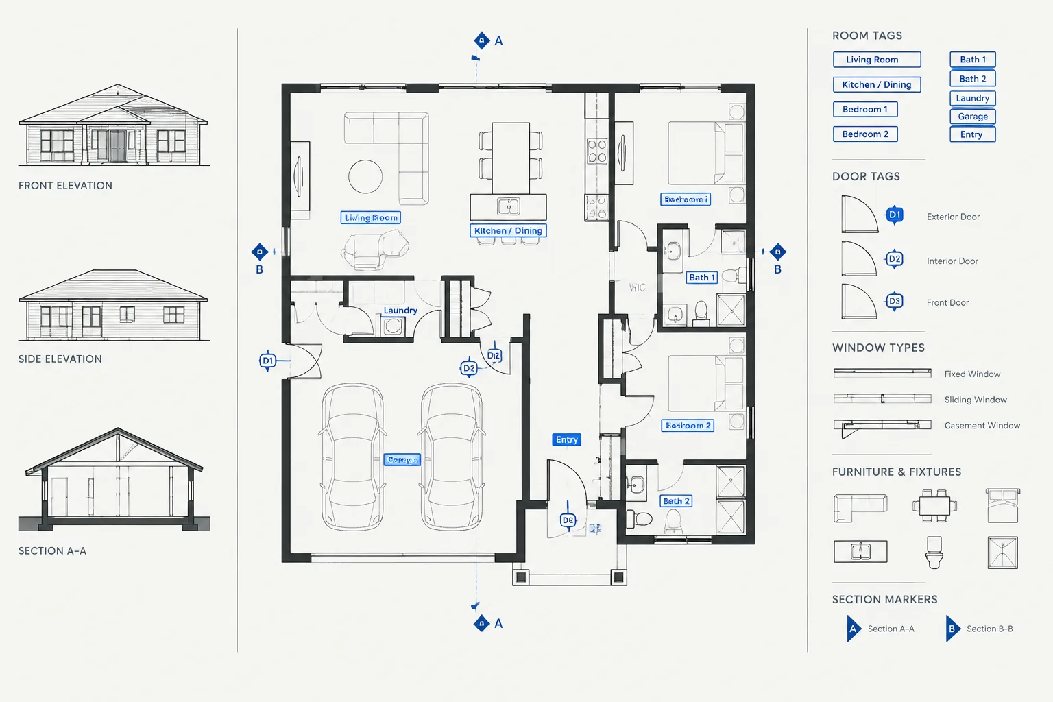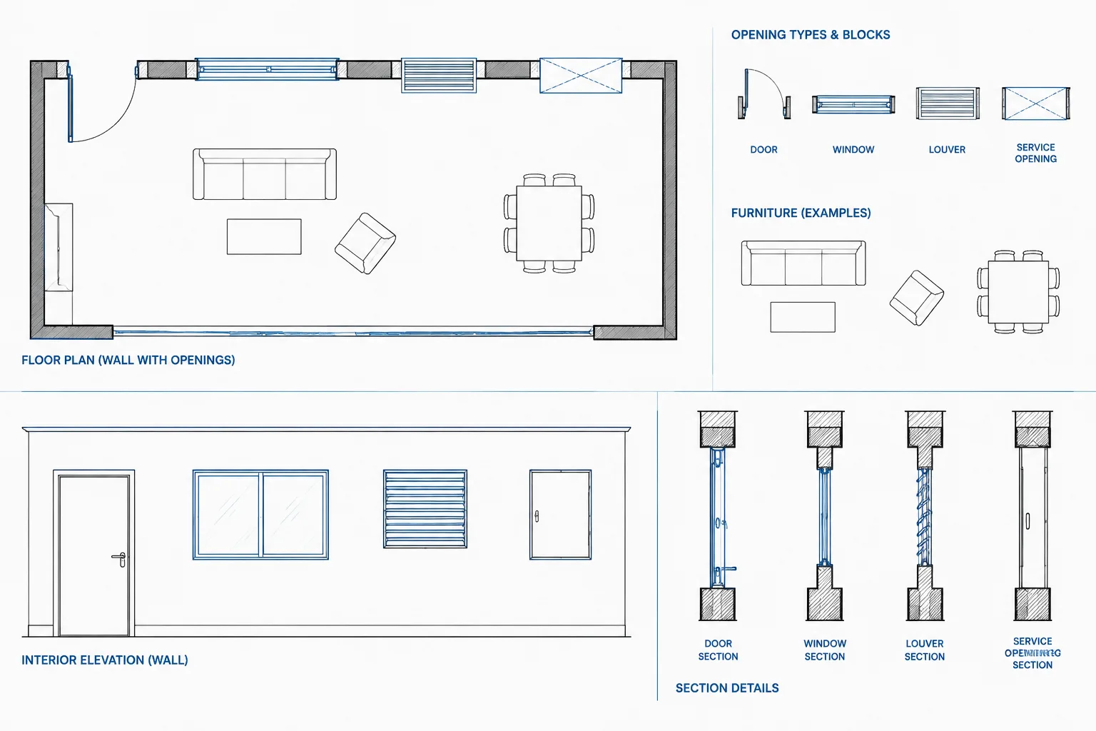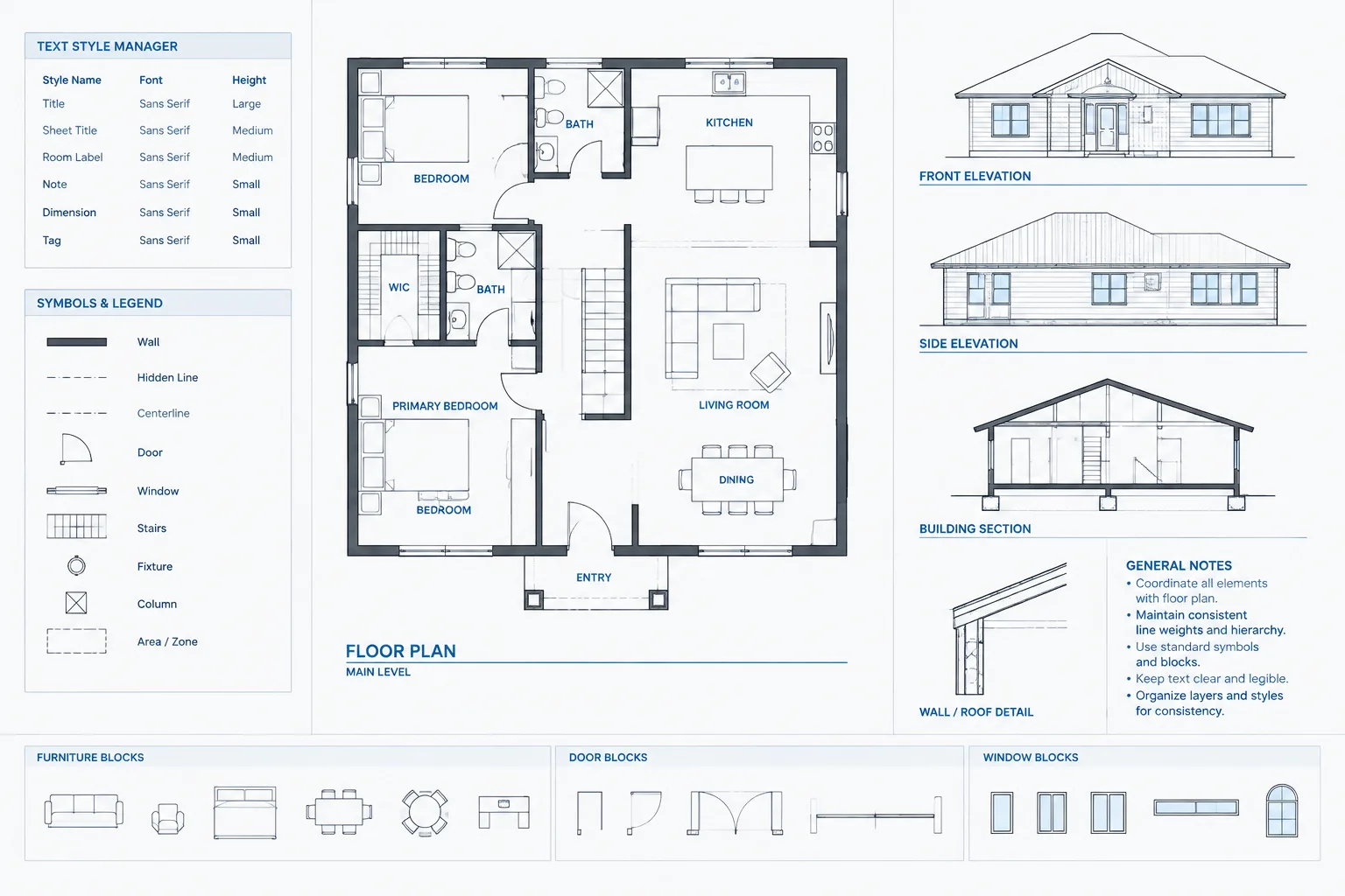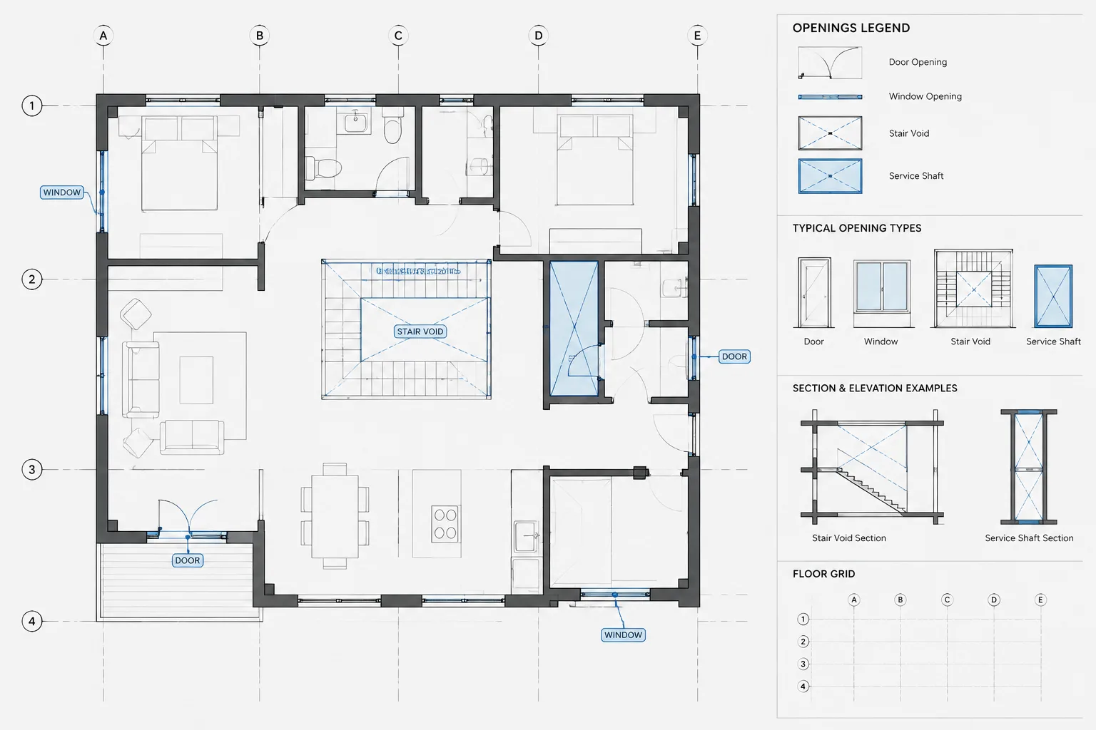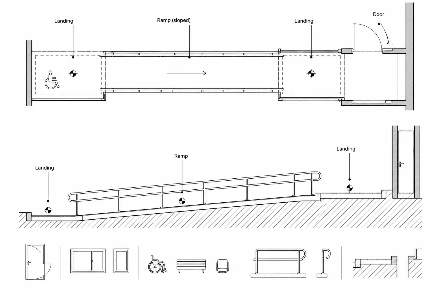
Drafting a ramp involves more than drawing parallel edges and adding a slope arrow. The plan geometry must remain consistent with elevations, landings, door clearances, rail layouts, structural support, and surrounding grading. This guide explains how to organize those relationships so the architectural ramp CAD documentation can be checked and revised as a coordinated system.
Ramps require more coordination than their simple plan geometry may suggest. A complete architectural ramp CAD drawing must communicate the route, elevation change, slope direction, landings, edges, adjacent doors, railings, drainage, and connections to surrounding floors or paving. If these elements are divided among unrelated drawings without a clear reference system, conflicts can remain hidden until late in documentation or construction.
This guide presents a practical workflow for drawing ramps in architectural CAD. It does not prescribe code-compliant dimensions or slopes. Those requirements vary by jurisdiction, building type, route classification, and project conditions, so every project must be checked against the applicable regulations and design criteria.
Begin with the Ramp’s Purpose and Context
Before drawing the ramp, identify why it is needed and what it connects. An exterior accessible route, a parking transition, a loading-area ramp, and an interior change in floor level may have different design and documentation needs.
Review the following source information:
- Existing and proposed floor or site elevations
- The total vertical change between connected surfaces
- Required route width and clearance criteria
- Door locations and door maneuvering areas
- Wall, curb, guard, and handrail conditions
- Structural slab or framing information
- Exterior grading and drainage direction
- Finish materials and threshold conditions
Do not estimate the ramp from appearance alone. Establish the controlling elevations and calculate the required run from the approved slope criteria. If the available plan length does not support the elevation change, the problem should be resolved before the drawing is detailed.
Build the Ramp from Controlling Geometry
Establish the route centerline or primary edge
Start with a simple polyline representing the route or one controlling ramp edge. This provides a stable reference for testing direction, turns, and landing locations. Once the route is confirmed, create the opposite edge using the required clear width and account for walls, curbs, rails, or other elements that may reduce usable space.
Avoid tracing a ramp with many disconnected line segments. Connected geometry is easier to measure, revise, and compare with the calculated run.
Place landings as distinct areas
Landings should be drawn as intentional surfaces rather than treated as incidental gaps between sloped runs. Show where each sloped segment begins and ends. At turns, confirm that the landing accommodates the route geometry and any required clearance.
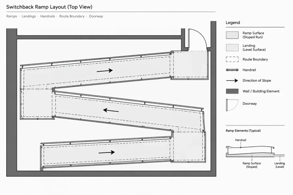
Where a door opens onto a landing, coordinate the landing with the door leaf, approach direction, wall returns, hardware side, and adjacent circulation. A landing that appears adequate before the door swing is added may not provide the required usable area.
Separate sloped and level surfaces
Use clear boundary lines to distinguish ramp runs from level landings and surrounding paving or flooring. These limits help coordinate elevation labels, finish patterns, structural edges, and drainage. They also make it easier to identify which portions of the route are included in a slope calculation.
Calculate and Verify Slope
A ramp should not be drafted solely by offsetting a convenient shape into the available space. Determine the vertical rise and horizontal run from coordinated elevations. Record the calculation in project notes or a checking worksheet, then compare it with the measured CAD geometry.
For a straight run, the basic relationship is:
Slope = vertical change divided by horizontal run
Use consistent units when performing the calculation. Do not include a level landing in the sloped run merely to improve the result. If several ramp runs connect through landings, verify each run independently and then check the complete elevation sequence.
Rounded labels can hide small discrepancies. Keep adequate calculation precision during design, even if the final annotation uses the project’s established rounding convention. Confirm that the stated endpoint elevations, run length, and slope describe the same geometry.
Show the Ramp Clearly in Plan
The plan should allow a reviewer to understand the ramp without reconstructing it from multiple views. Depending on project scope, useful plan information may include:
- Ramp edges and landing boundaries
- Slope arrows pointing consistently uphill or downhill
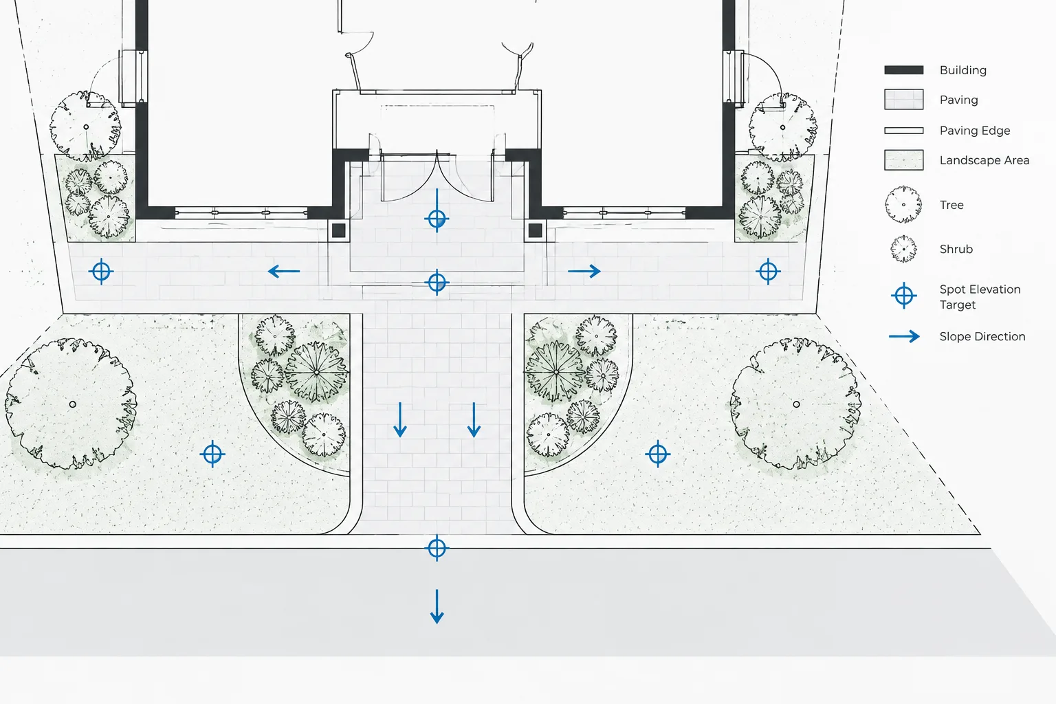
- Spot elevations at the top, bottom, and intermediate landings
- Door swings and nearby circulation
- Walls, curbs, wheel guards, guards, or open edges
- Handrails and their extensions where required
- Surface finish boundaries
- Drainage structures or nearby grading information
- Section and detail references
State or establish a project-wide convention for slope-arrow direction. An arrow used inconsistently can reverse the intended reading of the ramp. Pair the arrow with endpoint elevations whenever the direction might be ambiguous.
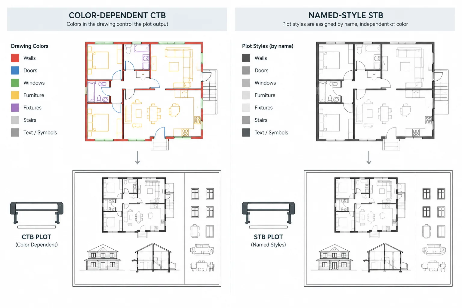
Control lineweights so that cut walls and primary boundaries remain dominant. Railings, slope arrows, finish patterns, and overhead information should support the drawing rather than obscure the route.
Develop a Coordinated Ramp Section
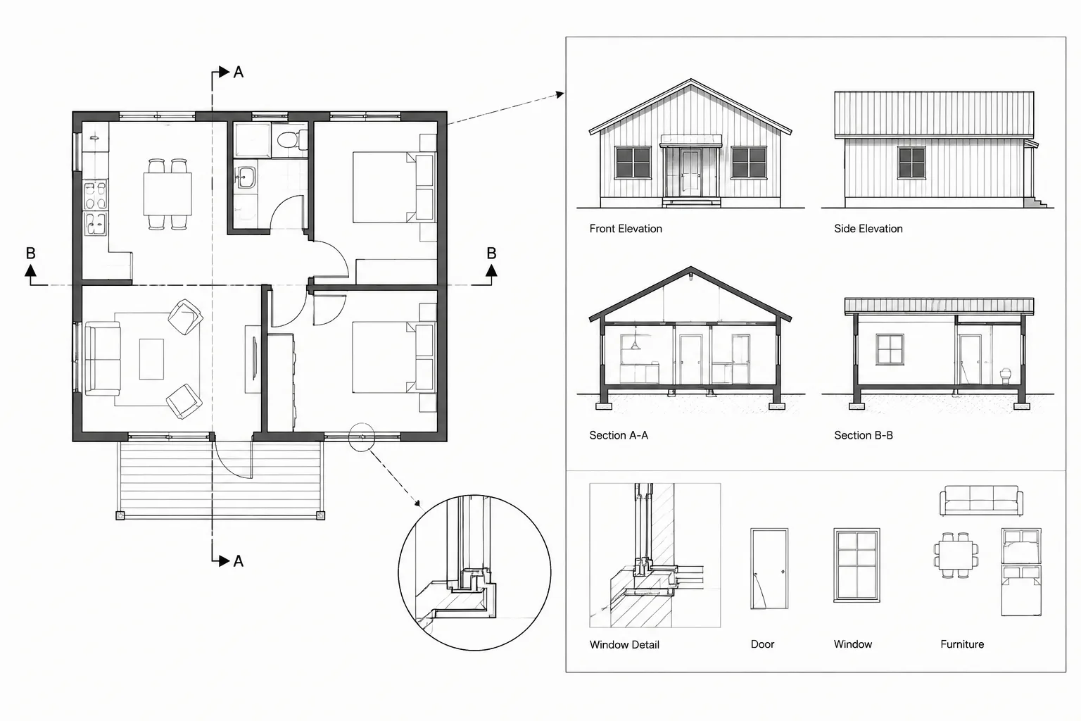
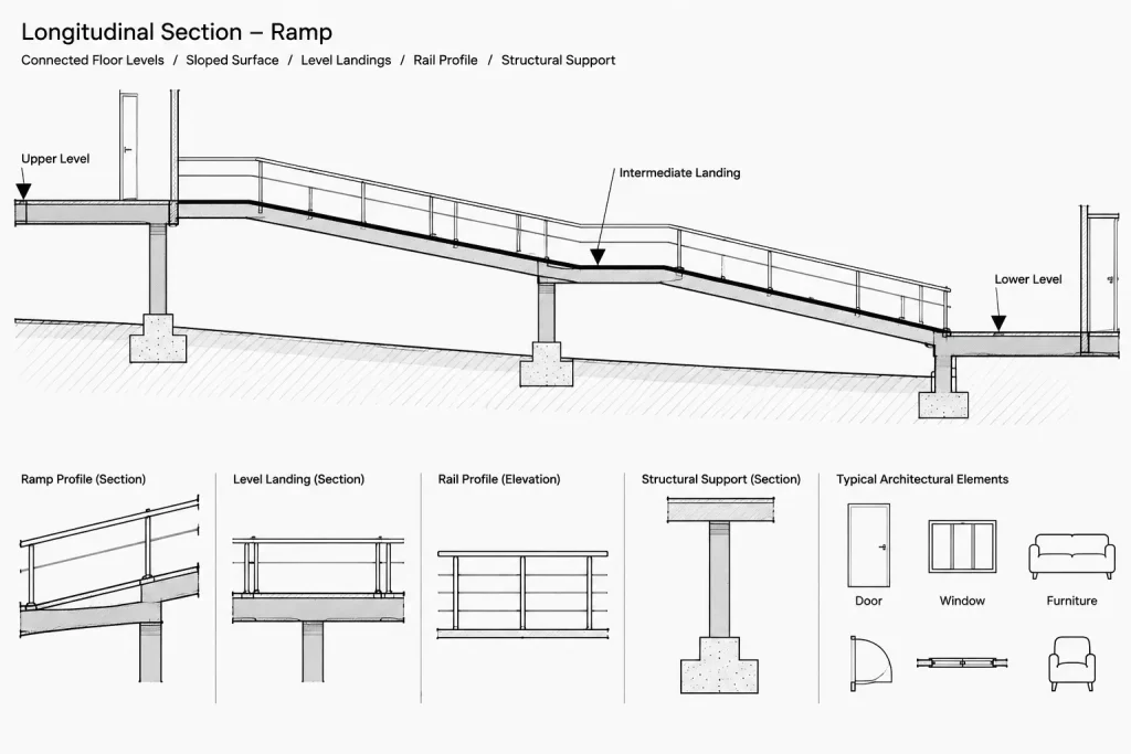
A plan explains the route, but a section verifies the vertical relationship. Cut the section through the most informative path, ideally showing the connected floor or paving levels, sloped surface, landings, and edge protection.
The section should coordinate:
- Top and bottom elevations
- Sloped run and level landing lengths
- Floor, slab, or paving thickness where relevant
- Transitions at each end
- Headroom beneath or above nearby construction
- Handrail and guard relationships
- Exterior drainage and water-management conditions
- Foundations or structural support when included in the architectural scope
Keep the plan and section geometrically related. If the plan run changes, update the section and recheck the slope. Do not allow the section to become a diagram that no longer matches the modeled or drafted plan length.
Coordinate Railings, Guards, and Edge Conditions
Handrails, guards, and ramp-edge treatments serve different purposes and should not be represented as a single generic line. Their requirements depend on the ramp configuration and applicable regulations.
In plan, distinguish rail faces from ramp boundaries and walls. At landings and turns, check for awkward overlaps, blocked clearances, and rail extensions that conflict with doors or circulation. In sections and details, show how rails relate to the walking surface, adjacent drops, curbs, walls, and supports.
Use a consistent block or linework convention for posts and brackets, but avoid adding every fastener at a general plan scale. Reserve connection information for enlarged details where it can be read and coordinated.
Coordinate Exterior Ramps with Site Drainage
Exterior ramps must be evaluated as part of the grading system, not as isolated architectural objects. Compare architectural elevations with the civil or landscape background and identify who controls each tie-in point.
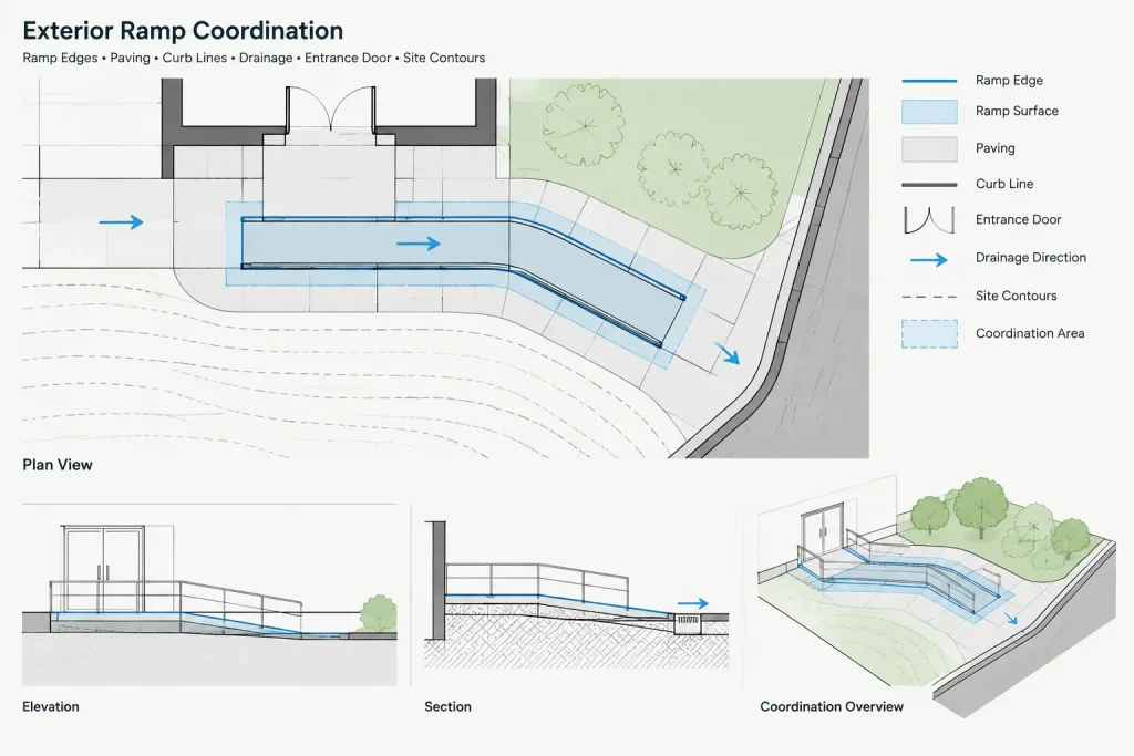
Review cross-slope direction, runoff at landings, drainage near doors, curb continuity, and transitions to sidewalks or parking surfaces. A ramp may meet its longitudinal design intent while still creating a low point or directing water toward an entrance.
When backgrounds are referenced into the architectural file, verify coordinates, units, and elevation assumptions before relying on them. Highlight unresolved discrepancies rather than adjusting the architectural linework silently.
Organize Ramp Information by Drawing Type
| Drawing | Primary information | Common coordination check |
|---|---|---|
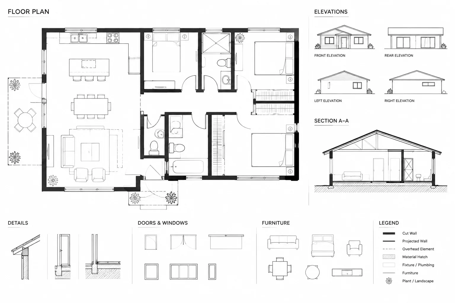
| Floor or site plan | Route, width, landings, arrows, doors, edges, and references | Confirm the complete path and adjacent clearances |
| Enlarged plan | Detailed rail layout, transitions, joints, and nearby fixtures | Check turns, door conflicts, and constructible geometry |
| Section | Elevations, rise, run, landings, support, and headroom | Compare endpoint elevations with the plan |
| Elevation | Rail profile, wall relationship, and exposed edges | Confirm continuity and termination conditions |
| Detail | Material transitions, edge construction, drainage, and attachments | Verify compatibility with architectural and structural assemblies |
Use Layers and Blocks Without Hiding Design Information
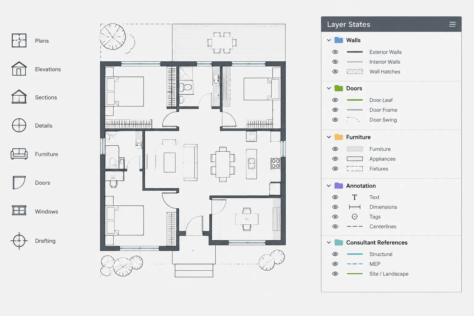
Place ramp surfaces, railings, annotations, finish patterns, and reference information on logical project layers. This allows different sheet views to emphasize the appropriate content without deleting geometry.
Blocks can be useful for repeated posts, directional symbols, spot-elevation markers, and section references. However, do not turn the entire ramp into an inflexible block while the design is still changing. Editable polylines and clearly grouped components are often easier to coordinate during development.
If a ramp assembly is reused, inspect its insertion units, scale, elevation data, layer properties, and text orientation. A reused symbol is only a starting point; it does not establish compliance for the current project.
Perform a Final Ramp Coordination Check
Before issuing the drawings, complete a focused review:
- Measure each sloped run directly in CAD.
- Recalculate slopes from the current endpoint elevations.
- Confirm that landings are shown as level where intended.
- Compare spot elevations across plans, sections, and details.
- Check door swings and circulation at every landing.
- Review handrail, guard, curb, and open-edge conditions.
- Verify exterior drainage and tie-ins with current backgrounds.
- Confirm that section markers reference the correct views.
- Plot the sheets and inspect arrows, labels, lineweights, and hatches at printed scale.
- Have the applicable code and accessibility criteria independently verified.
A reliable architectural ramp CAD drawing is not merely a sloped rectangle. It is a coordinated description of a circulation route in both plan and elevation. Building the drawing from verified levels, separating runs from landings, and checking every related view creates documentation that is clearer to review and easier to revise.
Establish a Coordination Hierarchy
Ramp drawings are easier to manage when the project team agrees on which information controls the design. Endpoint elevations and approved route criteria should guide the ramp geometry. The plan, section, enlarged views, and details should then describe the same solution rather than developing independently.
Identify the source responsible for each interface. Architectural drawings may control doors, finishes, and circulation, while structural drawings describe support conditions and site drawings establish surrounding grades. When information differs, record the discrepancy and confirm the controlling source before revising the ramp.
Keep a Ramp Change Review List
A minor revision can affect several views. When a ramp edge, landing, doorway, elevation, or tie-in changes, review every related plan, section, elevation, detail, annotation, and background reference. This focused change review helps prevent outdated geometry from remaining elsewhere in the drawing set.
- Geometry changes: Recheck run boundaries, landings, turns, and adjacent circulation.
- Elevation changes: Recalculate the slope and compare all elevation labels.
- Door changes: Review swings, approach areas, wall returns, and rail conflicts.
- Rail changes: Check continuity, terminations, supports, and open edges.
- Site changes: Revisit drainage direction, paving transitions, and tie-in points.
Use Drawing Comparisons as a Quality-Control Tool
Review the ramp plan and section together rather than checking each view in isolation. Trace the route from the lower connection to the upper connection and confirm that every sloped run and level landing appears in the same sequence. Then compare the enlarged plan and details for edge, rail, joint, and material-transition consistency.
A plotted review is also important. Information that appears distinct in the CAD workspace may merge when printed because of lineweight, hatch density, or overlapping annotation. The finished sheets should clearly separate route boundaries, railings, walls, finish patterns, slope graphics, and reference symbols.
Frequently Asked Questions
What information should control an architectural ramp CAD drawing?
The ramp should be based on verified endpoint elevations, approved slope criteria, required route clearances, and coordinated connection conditions. Available plan space alone should not determine the geometry.
Why should landings be drawn separately from sloped runs?
Separate boundaries clarify which surfaces are level and which are sloped. They also support accurate elevation annotation, slope checking, finish coordination, structural detailing, and drainage review.
Should the ramp plan and section be developed at the same time?
They should be coordinated throughout design development. The plan establishes the route and adjacent clearances, while the section verifies the vertical sequence, transitions, support conditions, and relationship between elevations and run lengths.
How should a ramp near a door be checked?
Review the door swing, approach direction, hardware side, wall returns, rail extensions, threshold, and usable landing area together. A door or railing revision can change whether the landing functions as intended.
How can exterior ramp drainage conflicts be identified?
Compare ramp elevations and surface directions with the current site background. Review runoff at landings, entrance thresholds, curb transitions, nearby drainage features, and connections to surrounding paving.
Can a reused ramp block establish project compliance?
No. Reused CAD content can assist drafting, but its geometry, units, layers, annotations, elevation assumptions, and project-specific criteria must be independently checked.