Effective bathroom accessories CAD documentation connects small wall-mounted and recessed items to the larger architectural drawing set. The work involves more than placing symbols: each item must remain consistent across enlarged plans, interior elevations, sections, schedules, and consultant backgrounds.
This guide explains how to build that coordination into the drafting workflow while keeping generic CAD geometry separate from verified product and project requirements.
Bathroom accessories may look secondary compared with walls, doors, and plumbing fixtures, but they can create significant coordination problems when added late. Dispensers may conflict with grab bars, mirrors may overlap outlets or wall lights, and recessed products may compete for space inside partitions. A clear bathroom accessories CAD workflow helps the design team identify these issues before drawings are issued.
The goal is not to fill a plan with detailed product graphics. It is to communicate each accessory’s location, mounting relationship, identification, and coordination requirements at the appropriate drawing scale. Exact dimensions and installation criteria should come from verified project documents, applicable regulations, and selected manufacturers rather than generic CAD blocks.
Define what belongs in the accessory scope
Begin by establishing which items the architectural drawings must show. The answer may vary by project, room type, procurement method, and consultant responsibilities. Commonly coordinated items include:
- Mirrors and mirrored cabinets
- Soap, towel, tissue, and hygiene-product dispensers
- Grab bars and other wall-mounted supports
- Hooks, shelves, changing surfaces, and waste receptacles
- Shower accessories, seats, curtains, and tracks
- Hand dryers and other powered equipment
- Recessed or semi-recessed accessory units
- Protective panels, partitions, and related mounting components
Create a project list before drafting individual rooms. For each item, identify who selects it, who supplies it, who installs it, and which discipline must coordinate it. Avoid assuming that every item near a plumbing fixture is part of the plumbing scope.
Use blocks as diagrammatic coordination tools
A bathroom accessory block should communicate the object’s footprint and mounting relationship without pretending to be a complete fabrication detail. A simplified block is usually more useful than a highly detailed manufacturer drawing at floor-plan scale.
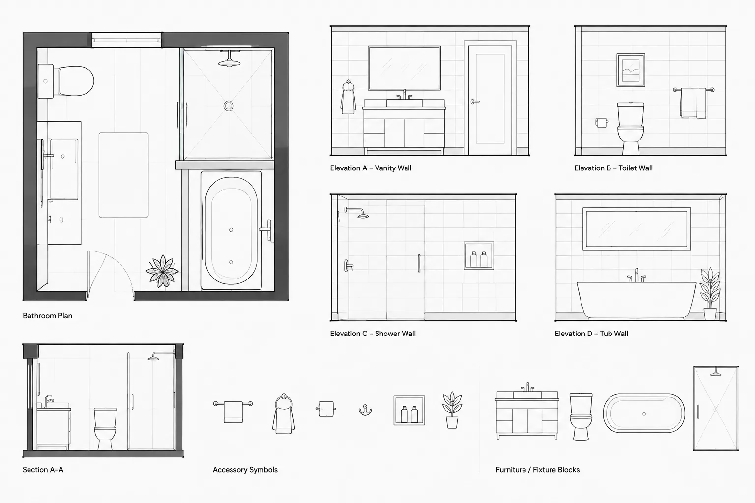
Prepare separate representations when an item needs to appear differently in plan, elevation, or section. A mirror, for example, may be a thin wall-mounted symbol in plan but a clear rectangular extent in an interior elevation. A recessed cabinet may also need a section symbol showing its relationship to the wall cavity.
Set reliable insertion points
Choose an insertion point that matches how the accessory is located in the project. Useful reference points include the centerline, mounting face, lower edge, or a consistent corner. The best choice depends on the information used to position the item.
Document the insertion-point convention in the block name, description, or library notes. Otherwise, users may align one block by its center and another by its outside edge without realizing the difference.
Separate graphic extents from required space
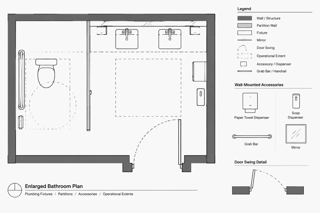
The visible object and the space needed to operate, refill, open, or service it are not always the same. Show operational extents with a distinct non-plotting or lightly plotted graphic when they are important to coordination. Examples include a cabinet door swing, dispenser cover, changing-surface movement, or maintenance access area.
Do not treat these diagrammatic extents as verified clearance requirements unless they have been checked against the selected product and governing project criteria.
Organize accessories with a clear layer strategy
Place accessories on layers that allow them to be isolated from plumbing fixtures, partitions, dimensions, and general furniture. The exact layer names should follow the project’s CAD standard, but the organization should distinguish at least the following functions:
- Accessory objects shown in plan
- Accessory objects shown in elevation or section
- Accessory tags and identification
- Operational or service extents
- Overhead items, where applicable
- Existing, removed, and new accessories on renovation projects
Avoid placing all bathroom content on one generic equipment layer. Separate control makes it easier to prepare enlarged plans, consultant backgrounds, demolition drawings, and presentation views without editing individual objects.
Coordinate the enlarged plan first
The enlarged bathroom plan is usually the best location for horizontal coordination. Start with the verified architectural background, including wall faces, door swings, partitions, casework, and plumbing fixtures. Attach consultant information as controlled references when available rather than copying disconnected linework into the drawing.
Place accessories in relation to stable architectural references such as finished wall faces, partition centerlines, fixture centerlines, or casework edges. Avoid locating an item only from another movable accessory. Chained relationships become difficult to maintain when the layout changes.
Check the door and partition zones
Door swings, wall stops, partition doors, and folding elements can collide with accessories. Review the full movement of each door rather than checking only its closed position. Also consider whether a projecting item is hidden behind an open door or prevents the door from reaching its intended position.
Review fixture-use areas
Accessories should support the intended fixture without obstructing movement or competing with another device. Use verified project criteria to assess reach, approach, and clearance conditions. A block downloaded from a library can help illustrate a concept, but it cannot confirm compliance or suitability by itself.
Identify recessed conditions
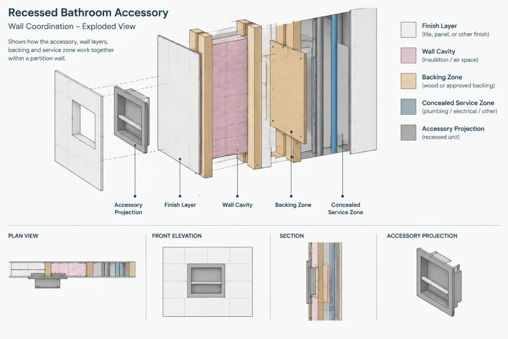
Mark recessed and semi-recessed items clearly. Their wall openings may affect studs, backing, insulation, fire-resistance assemblies, waterproofing, piping, conduit, or other concealed work. Flag these conditions for detailed coordination rather than representing them as ordinary surface-mounted rectangles.
Develop interior elevations as the vertical control drawings
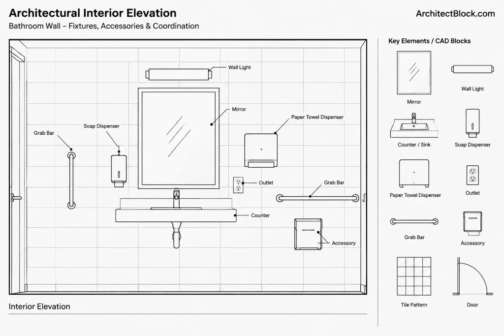
Plans show where an accessory sits along a wall, but interior elevations show its vertical relationship to fixtures, tile joints, outlets, lights, counters, and adjacent accessories. Build elevations from the same coordinated plan geometry so the two views do not drift apart.
Show the overall extents of each accessory and use centerlines or reference edges where they improve clarity. Mounting heights should be dimensioned from a clearly identified project datum or finished surface. Do not mix reference points without explanation; the top of an object, its centerline, and the location of its mounting hardware are different controls.
In tiled rooms, coordinate visible accessory edges with the tile layout where design intent requires alignment. Do not force an alignment that conflicts with verified mounting requirements or concealed construction. If the tile module and accessory location cannot both be maintained, identify the conflict for design resolution.
Coordinate sections and wall construction
A section is useful when an accessory projects significantly, folds, opens, or penetrates the wall. It can also clarify relationships that are ambiguous in plan and elevation, such as a recessed cabinet above a plumbing zone or an accessory mounted across a change in wall finish.
Review the wall type before indicating a recessed product. Confirm whether the partition has enough coordinated space and whether concealed utilities or structural elements occupy the same zone. Any required backing should be coordinated with the wall assembly and product installation information. A generic note to provide backing is not a substitute for identifying the affected location and responsibility.
Tag accessories without overcrowding the room
Use a consistent accessory identifier that connects plans and elevations to a schedule, specification, or equipment list. Keep tags outside dense fixture graphics where possible, and use orderly leaders that do not cross dimensions or conceal wall lines.
Attributes can help maintain identifiers and short descriptions within reusable blocks, but displayed information should remain concise. Long product descriptions, finish notes, and procurement information are generally easier to manage in a schedule than inside the plan.
| Drawing location | Primary information | Common coordination check |
|---|---|---|
| Enlarged plan | Horizontal position and projection | Doors, partitions, fixtures, and circulation |
| Interior elevation | Vertical position and alignment | Tile, counters, outlets, lights, and adjacent items |
| Section or detail | Depth, recess, opening, and mounting relationship | Wall assembly, backing, and concealed services |
| Accessory schedule | Identifier, description, location, and responsibility | Consistency with every drawing reference |
Run a focused coordination review
Before issuing the drawings, isolate the bathroom accessories and review them with the architectural background and relevant consultant files. A practical check should include:
- Every tagged accessory appears in the applicable schedule or list.
- Plan and elevation locations describe the same condition.
- Mirrors and cabinets do not conflict with lighting, outlets, controls, or trim.
- Powered accessories are coordinated with the electrical information.
- Recessed items have been reviewed against wall construction and concealed services.
- Door and partition movement is shown and checked.
- Operational graphics are distinguishable from actual object outlines.
- Existing, removed, relocated, and new items are visually distinct where required.
- Mounting criteria are based on verified project information rather than unverified block geometry.
Finish by plotting the relevant sheets at their intended output size. Accessory tags that look clear in model space may become crowded or unreadable on the sheet. A plot review also reveals weak line hierarchy, overlapping leaders, and inconsistencies between enlarged plans and elevations.
Treat downloaded CAD blocks as a starting point
Bathroom accessory DWG blocks can speed up drafting, especially when they provide coordinated plan and elevation views. Before using one, verify its units, scale, insertion point, layer content, linework, and orientation. Simplify excessive geometry and remove unrelated text or product information.
Most importantly, compare the block with the selected item and current project requirements. A clean CAD symbol improves communication, but product selection, mounting, accessibility, wall support, electrical service, and installation conditions still require project-specific verification.
Manage placeholders and design decisions clearly
Bathroom accessory layouts often begin before every product has been selected. Generic blocks can support early coordination, but their status should be clear to anyone reviewing the drawing. Avoid making a placeholder look more precise or product-specific than the available information supports.
When the design advances, compare the selected product information with the existing block rather than replacing graphics without review. Check the mounting reference, visible extent, projection, recess condition, operating movement, and required connections. A change that appears minor in elevation may affect a wall opening, electrical location, backing zone, or adjacent finish.
Track unresolved conditions
Use the project’s established issue-tracking method to record accessories that still require selection, consultant input, or wall-construction review. The drawing should communicate known design intent while making unresolved conditions visible to the team. This reduces the risk that a generic symbol will be mistaken for a completed coordination decision.
Keep the drawing set synchronized
Revisions should be checked by accessory identifier rather than by view alone. When an item moves in plan, review its elevation, related dimensions, leaders, wall support, service requirements, and schedule entry. When an elevation changes, confirm that the plan still represents the correct wall and orientation.
A useful final review follows each accessory from its tag to every place it appears. The objective is not maximum graphic detail, but a consistent chain of information from location and mounting relationship to description and responsibility.
Bathroom accessories CAD questions
Should a generic CAD block show exact product geometry?
No. A generic block should communicate the information needed at the drawing scale without implying that an unverified product has been selected. Exact geometry and installation conditions should be checked against current project documents and manufacturer information.
Why should plan and elevation blocks be coordinated?
The plan controls horizontal placement and projection, while the elevation controls vertical position and alignment. Coordinated representations help prevent the same accessory from appearing in conflicting locations across the drawing set.
How should recessed bathroom accessories be represented?
Identify the recess clearly and use a section or detail when the relationship to the wall assembly is not evident. The design team should also review concealed utilities, backing, finishes, and other construction occupying the wall zone.
What makes a useful insertion point for an accessory block?
The insertion point should match the reference used to locate the item, such as a centerline, mounting face, edge, or corner. Apply the convention consistently and document it in the block library so users do not align similar objects from different references.
Can a bathroom accessory block confirm accessibility or installation compliance?
No. A block is a communication and coordination tool. Compliance, mounting, support, operation, and installation must be verified using the project’s applicable criteria, selected products, and professional review.