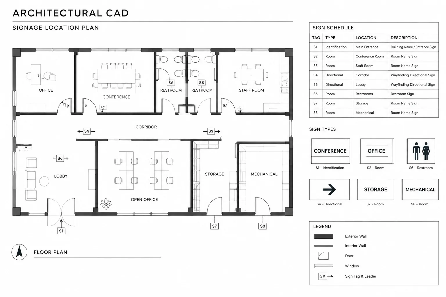
An architectural signage plan in CAD connects sign locations with type drawings, messages, mounting conditions, and schedule data. The drafting challenge is not simply placing markers; it is keeping those markers coordinated as rooms, doors, finishes, circulation routes, and owner requirements change.
The following workflow explains how to structure the drawings, distinguish repeated sign designs from location-specific content, and check the package before issue. Project teams should still verify regulatory language, accessibility criteria, fabrication requirements, and final installation conditions with the appropriate authorities and specialists.
An architectural signage plan identifies where signs occur, how they are referenced, and which drawings or schedules define their content and appearance. It may cover room identification, directional information, building directories, operational notices, exterior identification, and other project-specific sign types.
Although signs are relatively small components, they interact with doors, glazing, wall finishes, lighting, millwork, equipment, and circulation routes. A clear architectural signage plan in CAD should therefore function as a coordination drawing rather than a collection of isolated symbols.
This guide explains how to organize sign information across plans, elevations, details, and schedules without assuming that a generic CAD block or layout is appropriate for a particular project. Regulatory wording, accessibility provisions, mounting criteria, and life-safety requirements must always be verified against the project requirements and applicable rules.
Define the scope before drafting
Start by determining what the architectural signage package is expected to document. The scope may be limited to room signs, or it may include a broader family of interior and exterior signs. Confirm whether signs supplied with equipment, tenant branding, temporary signs, and code-related notices are included or documented elsewhere.
A practical scope list might distinguish among:
- Room and space identification signs
- Directional and wayfinding signs
- Directories and information panels
- Door, wall, glazing, or ceiling-mounted signs
- Exterior building and site identification
- Operational, warning, or restricted-access notices
- Signs integrated with reception desks, millwork, or feature walls
- Owner-furnished or vendor-designed graphics
This early classification prevents a common problem: using one generic symbol for signs that require different support conditions, content, finishes, or consultant coordination.
Choose a drawing structure
Signage information is usually easier to manage when it is divided among several coordinated drawing types. Trying to place every message, material note, and mounting instruction directly on a floor plan can make the plan unreadable.
| Drawing component | Primary purpose | Typical information |
|---|---|---|
| Signage location plan | Shows where signs occur | Tags, orientation, host surface, relevant room or door |
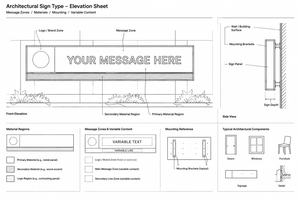
| Sign type elevation | Defines the visible arrangement | Message zones, graphics, materials, edges, and mounting concept |
| Mounting detail | Explains attachment and interfaces | Wall, glazing, millwork, post, ceiling, or other support condition |
| Sign schedule | Organizes repeated data | Type, message, location, quantity, finish, remarks, and responsibility |
| Graphic or message schedule | Lists variable content | Room names, numbers, directional text, symbols, or approved wording |
Not every project needs all five components. The objective is to place each kind of information where it can be edited and checked efficiently.
Prepare the CAD background
Use a coordinated architectural floor plan as the background for the signage location plan. The background should show enough context to relate each sign to rooms, doors, corridors, stairs, elevators, and major fixed elements, but it does not need every construction note or material hatch from the primary plan.
Before placing signs, confirm that the background reflects the current room numbering, door locations, wall configuration, and circulation layout. Signage developed from an outdated plan can retain incorrect room names or point toward routes that no longer exist.
If the plan is externally referenced, control its graphic appearance through an established layer or display workflow. Keep the signage information visually dominant while preserving enough architectural context to understand each location.
Create a clear sign location symbol
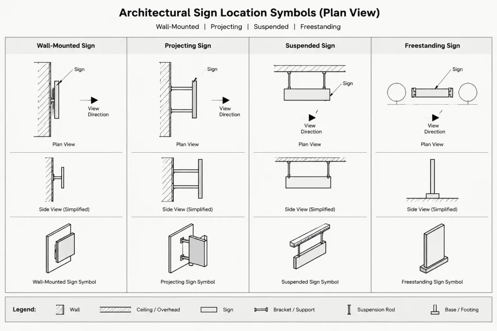
A plan symbol should communicate location and orientation without pretending to represent the sign’s exact physical size. A simple marker, leader, or directional indicator is often more legible than drawing the full sign outline at a small plan scale.
A useful sign marker can include:
- A unique sign type or item identifier
- A leader to the intended mounting location
- An orientation cue when the viewing direction matters
- A distinction between wall-mounted, projecting, suspended, and freestanding signs
- An optional attribute for variable message or schedule reference
Use one insertion-point convention throughout the drawing. For example, the insertion point may represent the center of the sign, the point of attachment, or the tip of the leader. Record the convention in the CAD standard or symbol legend so that moved and rotated blocks remain predictable.
Avoid ambiguous placement
Do not place a tag loosely in the middle of a room when the sign must be associated with a particular doorway, wall face, or approach direction. A reviewer should be able to tell which surface receives the sign and which circulation path it serves.
Where several signs are close together, separate their leaders and use enlarged plans or local details rather than stacking unreadable symbols.
Organize signs by type and unique message
A sign type and a sign message are not always the same thing. Several room signs may share the same construction, finish, and mounting method while displaying different room names or numbers.
Separate repeated physical properties from variable content:
- Sign type: Describes the common design, material concept, configuration, and mounting method.
- Sign item: Identifies a particular installed sign at a specific location.
- Message: Records the text, number, arrow, symbol, or other variable information.
This structure reduces duplicated drafting. One type elevation can define a family of signs, while the schedule lists each location and its individual message.
Draft sign type elevations
Create a type elevation for each genuinely different sign configuration. Draw the sign face with a clear outline and organize text, symbols, message fields, borders, and material zones so that changes can be made without rebuilding the drawing.
Type elevations should distinguish fixed information from placeholders. If the final wording comes from a message schedule, use a neutral field label rather than inserting sample text that could be mistaken for approved content.
Include only verified dimensions and specifications. If the sign vendor or graphic designer will finalize typography, color, fabrication, or attachment, label the drawing accordingly and avoid presenting preliminary graphics as fabrication-ready information.
Coordinate mounting conditions
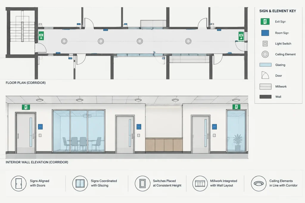
Sign placement must be checked against the surface and nearby components. A marker that appears acceptable on plan may conflict in elevation with glazing, wall panels, door frames, switches, artwork, casework, or lighting.
Review each mounting condition for:
- Available wall or panel area
- Door swing and door-frame relationships
- Glazed sidelights and transparent partitions
- Changes in wall finish or decorative reveals
- Millwork doors, drawers, and access panels
- Electrical devices and controls
- Ceiling elements for suspended signs
- Landscape, paving, utilities, and sightlines for exterior signs
Use interior elevations where the vertical relationship is important. For unusual substrates or concealed attachments, provide a detail or identify the responsible specialist rather than relying on a generic note.
Build a manageable sign schedule
The sign schedule should support coordination without becoming a substitute for every drawing. Choose fields that the project team can maintain consistently. Useful fields may include item number, sign type, floor, room or location, message, mounting condition, finish reference, quantity, remarks, and responsibility.
Establish whether quantities are counted by individual item, repeated location, or sign type. Do not mix these methods within the same schedule. Where a sign has messages on more than one face, describe that condition clearly instead of assuming that one schedule row communicates both sides.
If schedule data is extracted from block attributes, keep attribute names and values consistent. If the schedule is maintained manually, compare it systematically with the plan during each drawing update.
Use layers to separate information
A dedicated layer structure makes it easier to display signage differently on working plans and issued sheets. Depending on the office standard, separate layers may be useful for sign markers, leaders, sign text, elevation graphics, mounting information, and temporary coordination notes.
Do not place every sign component on one generic annotation layer. Separating objects by function allows reviewers to isolate sign locations, suppress working notes, and apply an appropriate plotted hierarchy.
Keep architectural background geometry separate from signage objects. Avoid editing walls, doors, or room tags in the signage file merely to improve the appearance of the sign plan; corrections should occur in the responsible source drawing.
Coordinate with related drawings
Signage information frequently depends on data maintained elsewhere in the drawing set. Compare the signage package with:
- Floor plans and room tags
- Door numbers and door schedules
- Interior elevations and finish plans
- Reflected ceiling plans
- Furniture, equipment, and millwork plans
- Electrical device and lighting layouts
- Site and landscape plans
- Owner, tenant, or graphic-design information
Room numbering deserves particular attention. When a room number changes, the related sign message, schedule entry, door association, and wayfinding information may also need revision.
Run a final signage CAD check
Before issuing the drawings, review the package from both a drafting and wayfinding perspective. Walk through the plan visually as if approaching each destination rather than checking tags only in numerical order.
- Confirm that every scheduled sign appears on the plan.
- Confirm that every plan tag has a corresponding schedule or type reference.
- Check messages against the current room and door information.
- Verify leaders, orientation, and mounting surfaces.
- Look for signs obscured by doors, furniture, glazing, or millwork.
- Check that type elevations match the schedule terminology.
- Remove obsolete signs and duplicate identifiers.
- Plot at the intended sheet scale and inspect tag readability.
- Resolve temporary notes, unverified placeholders, and coordination clouds.
- Identify regulatory or specialist information that still requires verification.
Keep the plan focused on coordination
A successful architectural signage plan does not need to show every fabrication decision. Its main job is to establish a reliable relationship among location, type, message, orientation, and mounting condition.
By separating repeated sign types from variable messages, using precise location markers, and coordinating the signs with architectural backgrounds and schedules, the CAD package becomes easier to review and update. It also gives graphic designers, fabricators, owners, and construction teams a clearer basis for completing their respective work without treating an unverified CAD symbol as a finished project solution.
Establish ownership of signage information
Before the package advances, identify which project participant controls each category of information. The architect may coordinate locations and architectural interfaces, while an owner, graphic designer, consultant, or fabricator may control wording, branding, typography, fabrication, or attachment design. Recording these responsibilities helps prevent preliminary information from appearing final.
Choose a source of truth for each field
Room names should come from the approved room data used by the architectural drawings. Door references should follow the coordinated door information. Sign messages should come from the approved message record rather than being retyped independently in plans, elevations, and schedules.
When the same information must appear in several places, decide which drawing or schedule governs and treat the other appearances as coordinated references. This reduces conflicting edits and makes review comments easier to resolve.
Use a controlled revision workflow
Signage can be affected by apparently minor architectural revisions. A moved door may change the mounting surface, a renamed room may change the sign message, and a revised circulation route may affect directional information. Review signage whenever related backgrounds or room data are updated.
- Identify the architectural change and the signage records it may affect.
- Update the governing data source before editing dependent graphics.
- Compare plan markers, type references, messages, and mounting conditions.
- Flag information that still requires owner, consultant, or vendor confirmation.
- Plot the affected sheets and inspect the revised information in context.
Prepare the package for handoff
A clean handoff should make it clear which information is coordinated, which is illustrative, and which remains subject to specialist development. Remove abandoned blocks and working notes, confirm that references resolve correctly, and use consistent identifiers in the plan, elevations, details, and schedules.
Do not rely on a visually complete CAD drawing as proof that sign content, compliance, fabrication, or attachment has been approved. The issued package should communicate its limits as clearly as it communicates sign locations.
Architectural Signage Plan FAQ
What is the difference between a sign type and a sign item?
A sign type represents a repeated physical design or mounting concept. A sign item represents a particular sign at a specific location and may carry a unique room name, direction, symbol, or other message.
Should a plan symbol show the actual size of the sign?
Not necessarily. On a location plan, clarity is usually more important than depicting the exact sign outline. The symbol should reliably indicate the mounting point, associated surface, orientation, and reference to supporting information.
Which document should control the sign message?
The team should designate a single approved source for variable wording and identifiers. Plans, elevations, and schedules should then be checked against that source rather than edited independently.
Can a signage schedule be maintained manually?
Yes, provided it is compared systematically with the plan and related drawings after revisions. Attribute-based data can reduce repeated entry, but it still requires consistent naming, placement, and review.
When should an interior elevation be used for signage?
Use an interior elevation when vertical placement or relationships with doors, glazing, finishes, devices, casework, artwork, or other wall elements cannot be understood clearly from the plan.
Does a generic signage CAD block confirm project compliance?
No. A generic block can support drafting organization, but it does not verify required wording, accessibility provisions, mounting criteria, life-safety obligations, fabrication, or suitability for a particular installation.