
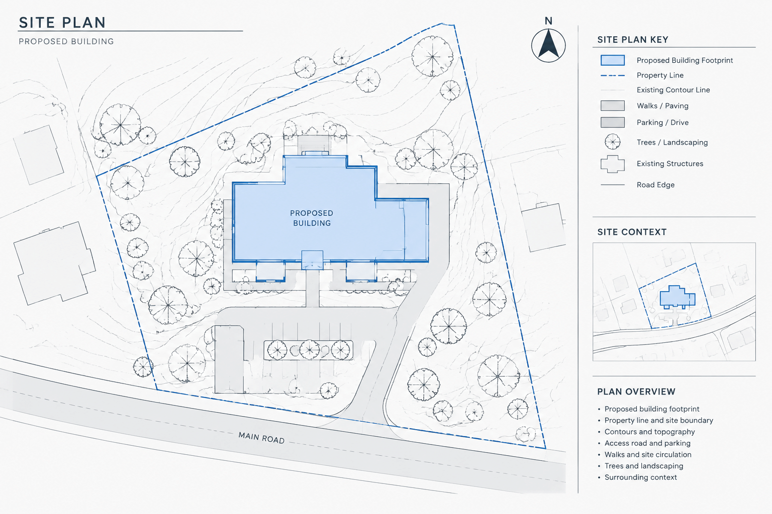
An architectural site plan connects the building design to its parcel, access points, surrounding features, and consultant information. Although it may begin with a survey, it is not simply a survey file with a building footprint placed on top. The architectural drawing must organize the available information into a readable plan while preserving the accuracy and authority of the original source.
A reliable architectural site plan CAD workflow separates source data from project graphics, establishes a clear responsibility for each element, and avoids redrawing information that should remain linked to a survey or civil base. The following process is suitable for early design, coordination, and drawing production, but the required content should always be confirmed for the project type and jurisdiction.
Understand the purpose of the site plan first
Before editing a DWG file, determine what the site plan needs to communicate. A planning or presentation plan may emphasize the building, pedestrian routes, parking, and landscape organization. A construction-oriented architectural plan may also need entrances, exterior stairs, accessible routes, service areas, consultant references, and detail callouts.
The drawing should not imply a level of accuracy that the source information cannot support. Concept sketches, online mapping, aerial imagery, and owner-provided diagrams may help with preliminary studies, but they do not replace a verified survey when boundaries, easements, elevations, or legal site features matter.
Review the survey or base drawing before using it
Open the source file independently and inspect it before attaching it to the architectural model. Do not assume that a file is ready merely because it is in DWG format.
- Confirm drawing units. Check a known feature or coordinate with the surveyor’s documentation rather than relying only on the file’s unit setting.
- Identify the coordinate system or project origin. Determine whether the drawing uses survey coordinates, a consultant-defined project origin, or a local working origin.
- Review layer names and visibility. Locate boundaries, contours, spot elevations, utilities, paving, vegetation, structures, and annotation.
- Look for duplicate or outdated information. Survey files may contain alternate linework, historical backgrounds, or data that was retained for reference.
- Check file orientation. Understand the relationship between drawing north, project north, and the intended sheet orientation.
- Read notes and qualifications. Important limitations may appear in the survey title block, transmittal, or accompanying documentation.
If something is unclear, request clarification from the responsible source instead of interpreting ambiguous geometry as verified information.
Preserve the survey as a referenced source
In most coordinated workflows, the survey should remain a separate file and be attached as an external reference. This protects the source, makes updates easier to track, and reduces the temptation to modify consultant information inside the architectural drawing.
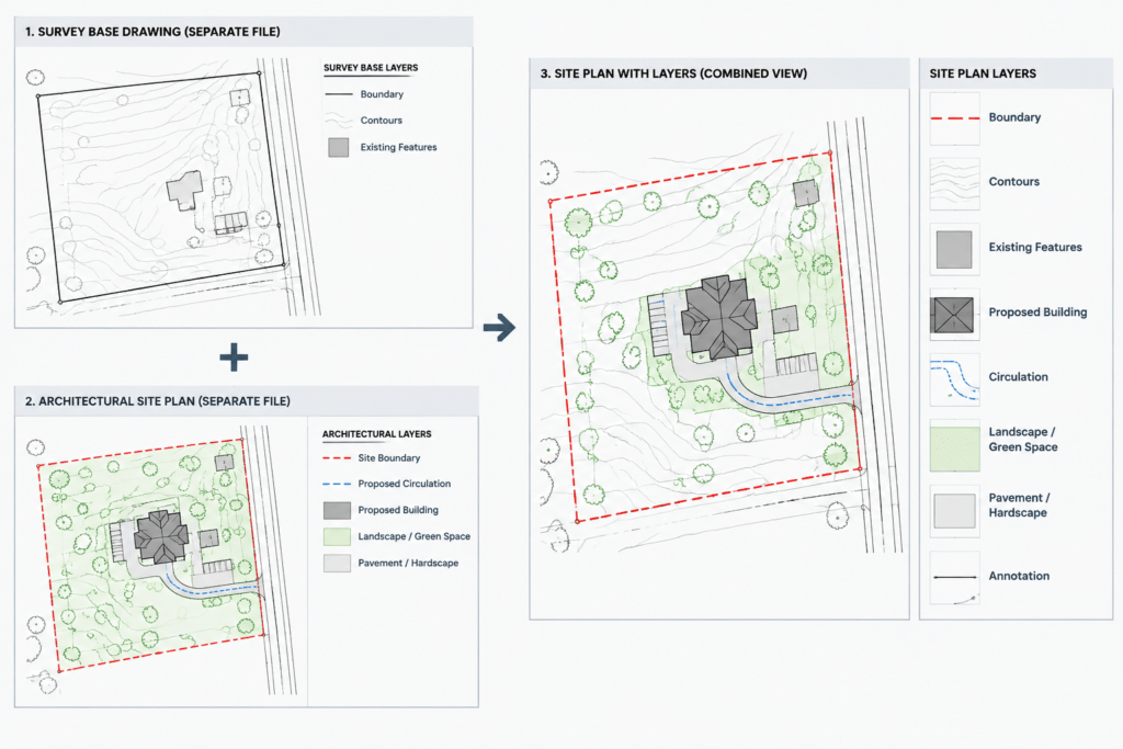
Retain the agreed insertion point, rotation, and scale. Moving a survey close to the CAD origin may feel convenient, but an undocumented move can break coordination with civil, landscape, structural, and utility drawings. If the project team needs a local architectural origin, establish a documented relationship between that origin and the shared base rather than shifting files independently.
Use an overlay-style reference relationship where appropriate to prevent unnecessary nested references from propagating into other files. Reference practices should follow the project’s agreed CAD protocol.
Separate source information from architectural additions
Create architectural site-plan geometry in the architectural model, not inside the survey reference. Typical additions may include the proposed building footprint, entrances, overhangs, exterior circulation, architectural site walls, service zones, parking concepts, and drawing annotations.
Assign these elements to layers according to their purpose and ownership. A simple organization might distinguish among:
- Existing survey information
- Proposed building outlines
- Elements above or below the primary plan cut
- Pedestrian and vehicle circulation
- Architectural site features
- Landscape or civil references
- Text, dimensions, symbols, and callouts
- Demolition or removal information, when applicable
Layer names should follow the office or project convention. The important principle is that users can identify what came from the survey, what was drawn by the architect, and what belongs to another consultant.
Build the proposed building footprint carefully
The site-plan footprint should be derived from the coordinated architectural floor plan rather than sketched separately. Referencing a simplified footprint file or using coordinated architectural geometry reduces discrepancies when the building changes.
Decide which projections need to appear. Roof overhangs, canopies, balconies, exterior stairs, ramps, loading covers, and below-grade extents may require different linetypes or graphic treatments. Do not show every interior wall on a general site plan unless it serves a specific coordination purpose.
Locate entrances clearly and coordinate them with exterior paths, drives, drop-off areas, and changes in grade. The site plan is often where circulation conflicts become visible, including doors opening toward constrained landings, walkways that do not meet entrances, or service traffic crossing primary pedestrian routes.
Control the graphic hierarchy
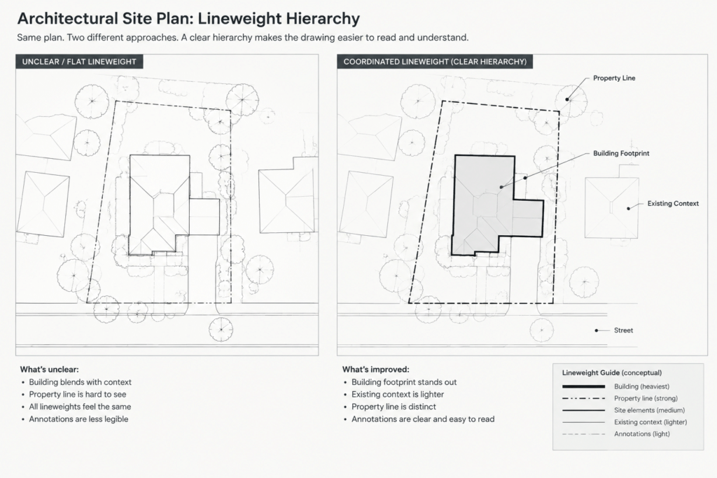
A site plan contains many overlapping systems, so lineweight and contrast are essential. The proposed building commonly needs the strongest emphasis. Property and regulatory reference lines should remain identifiable without overpowering the plan, while existing survey detail can be screened or assigned a lighter plotted appearance.
| Information group | Recommended graphic role |
|---|---|
| Proposed building | Primary visual emphasis with a clear footprint |
| Property and easement information | Distinct linetypes and labels based on verified source data |
| Existing context | Secondary background information |
| Proposed circulation and site features | Clear but subordinate to the building |
| Contours and elevation data | Readable without creating a dense background |
| Annotations and callouts | Consistent text hierarchy with minimal linework conflicts |
Use hatches sparingly. Large areas of dense paving, landscape, or roof hatching can obscure contours, utilities, and dimensions. Test the drawing at its intended plotted scale rather than judging only from a zoomed-in model-space view.
Add site-plan annotation with clear ownership
Common annotations include the project boundary, street names, building identification, entrances, parking and loading areas, exterior features, north indication, drawing scale, dimensions, and references to enlarged plans or details. The actual annotation set depends on the drawing’s purpose.
Dimensions should come from coordinated and verifiable geometry. Avoid dimensioning to approximate aerial features or tracing-based backgrounds. Clearly distinguish surveyed boundaries and elevations from proposed architectural dimensions.
Property lines, easements, setbacks, flood information, utility locations, and similar constraints should not be invented or inferred. Show them only from an appropriate project source, and identify their status when the information is preliminary.
Coordinate grading without assuming civil responsibility
Architectural site plans often need enough vertical information to explain entrances, exterior stairs, ramps, terraces, and relationships to lower floors. That does not mean the architectural team should independently create final grading from incomplete information.
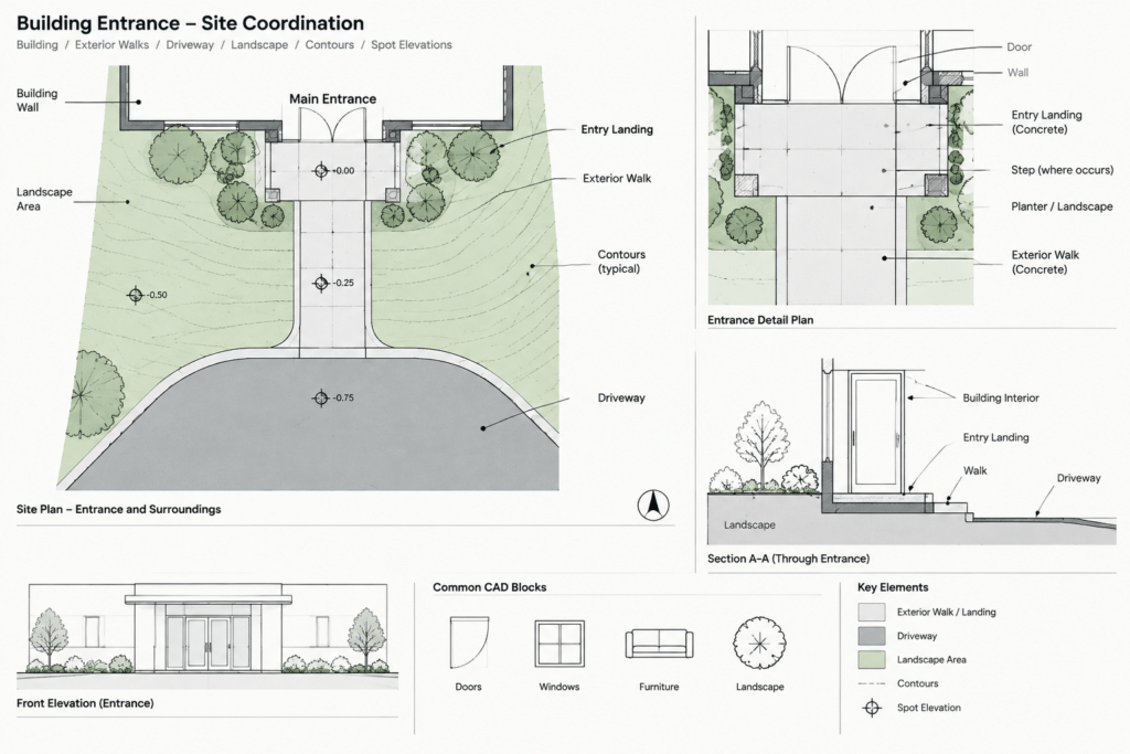
Reference verified contours and spot elevations, and coordinate proposed levels with the responsible consultant. Use callouts to direct readers to civil, landscape, or structural drawings where those disciplines control the design. If architectural and civil drawings show the same elevation or edge condition, compare them during every major update.
Create the sheet view deliberately
Set up the site plan in a paper-space viewport at the required presentation scale. Rotate the view only through a documented sheet workflow; avoid rotating or relocating the underlying coordinated base merely to make it fit the page.
Crop or freeze information that is outside the drawing’s purpose, but retain enough surrounding context to explain access and adjacent conditions. Place the north symbol where it is easy to find, and confirm that it reflects the displayed orientation. Coordinate the title, scale notation, key plan, legends, and reference callouts with the rest of the drawing set.
Run a site-plan quality-control check
Before issuing the drawing, review both the CAD model and a plotted output. A practical check should include:
- The latest survey and consultant references are loaded.
- Units, scale, coordinates, insertion points, and rotation are correct.
- The building footprint matches the current architectural plans.
- Entrances align with exterior walks, drives, stairs, or landings.
- Existing, proposed, and removal work are visually distinguishable.
- Property-related information comes from a verified source.
- Contours, spot elevations, and proposed levels do not conflict.
- Parking, service, and pedestrian circulation are coordinated.
- Text, symbols, dimensions, and leaders remain legible at plot scale.
- Reference files and layer states are suitable for transmittal or archiving.
Treat the site plan as a coordination drawing
A strong architectural site plan is more than a diagram of the lot. It is a coordination interface between the building and the work of survey, civil, landscape, structural, utility, and planning teams. Maintaining separate source files, documenting origins, deriving the footprint from the architectural model, and controlling the graphic hierarchy make the drawing easier to update and trust.
Most site-plan errors begin with uncontrolled assumptions: an unverified scale, a moved base file, a traced boundary, or an outdated footprint. A disciplined architectural site plan CAD workflow makes those assumptions visible and replaces them with coordinated, reviewable information.


