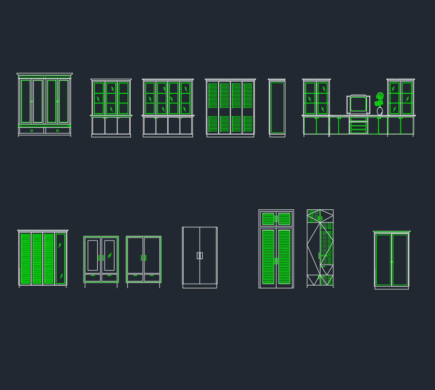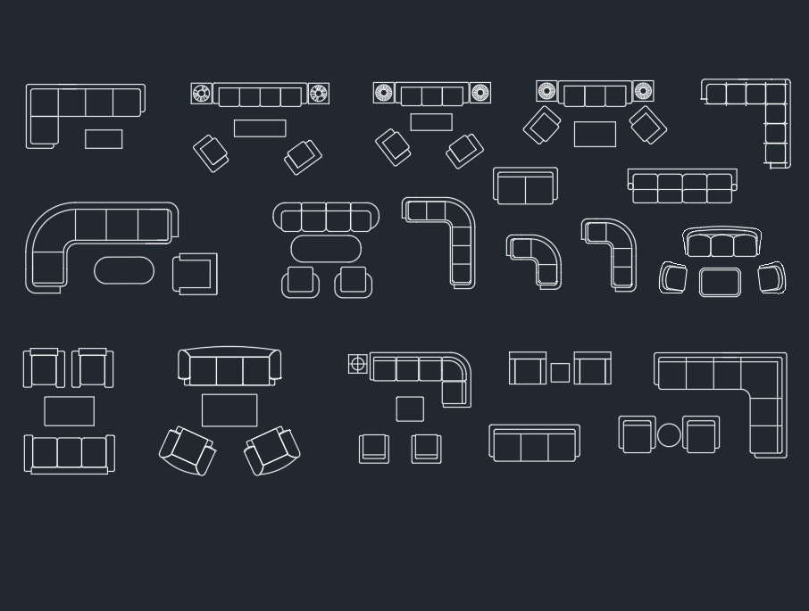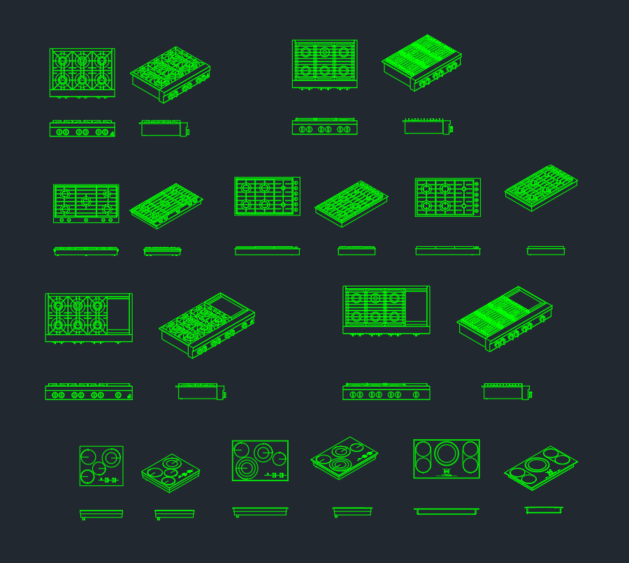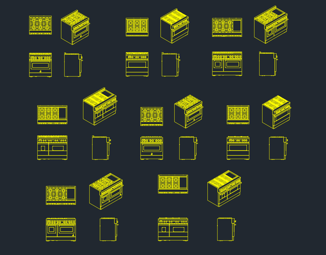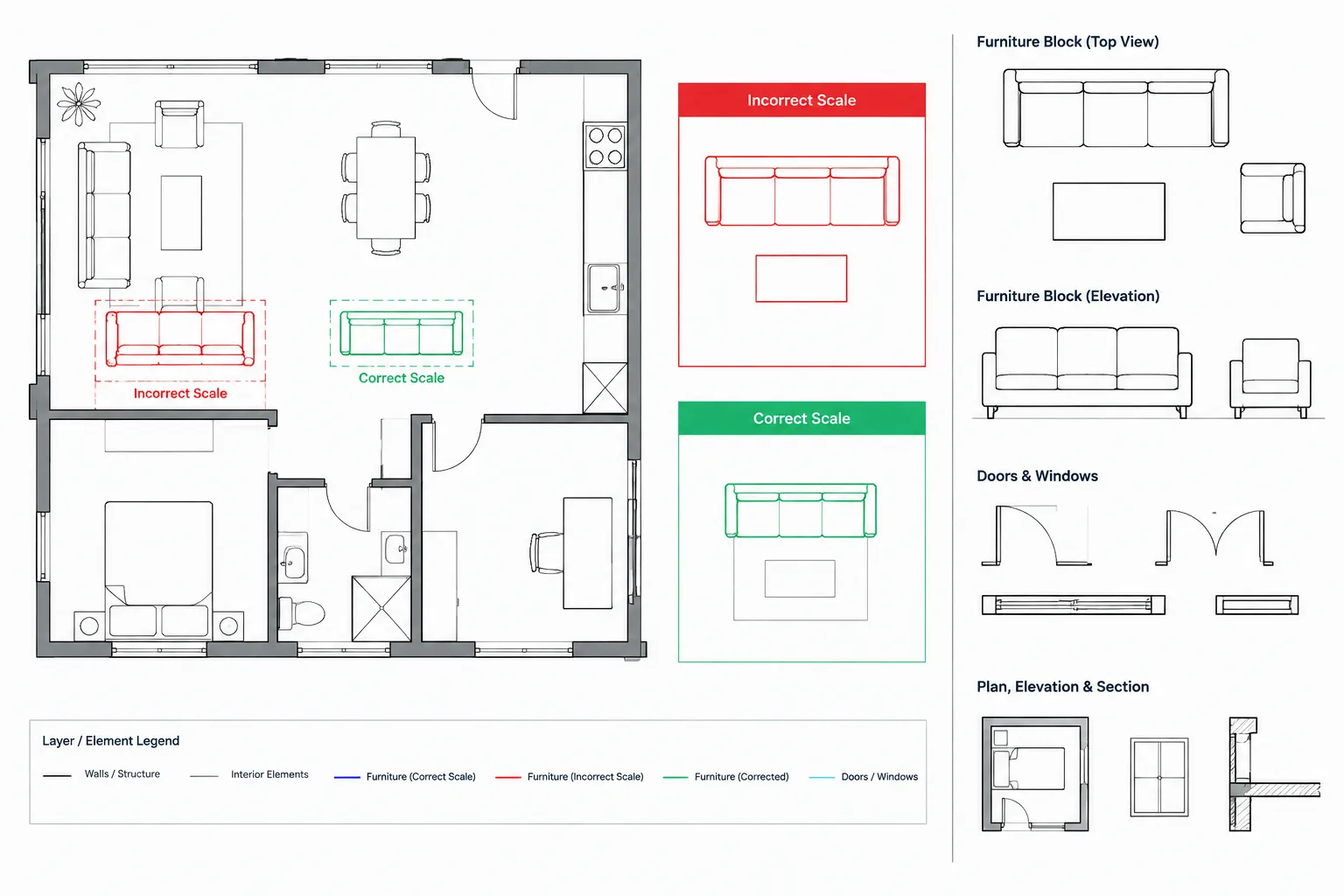
Incorrectly scaled CAD blocks can disrupt floor plans, equipment layouts, elevations, schedules, and drawing coordination. The visible size problem may originate in the source geometry, drawing-unit metadata, the inserted reference, a nested definition, or an existing block already stored in the project.
This guide presents a controlled diagnostic approach rather than relying on trial-and-error scaling. The goal is to identify where the mismatch occurs, correct the appropriate part of the DWG workflow, and preserve a dependable block for future use.
A CAD block that inserts far too large or too small is not always a simple scaling problem. The source file may use a different unit convention, contain incorrectly sized geometry, include nested blocks, or represent a paper-sized annotation rather than a full-size building component. Applying an arbitrary scale factor may make the object look reasonable, but it can also conceal a problem that returns when the block is reused, replaced, or measured.
A reliable correction begins by identifying what the block represents and how its source geometry was created. The following workflow is intended for furniture, fixtures, doors, equipment, symbols, and other architectural DWG content brought into an active project.
Why CAD Blocks Insert at the Wrong Size
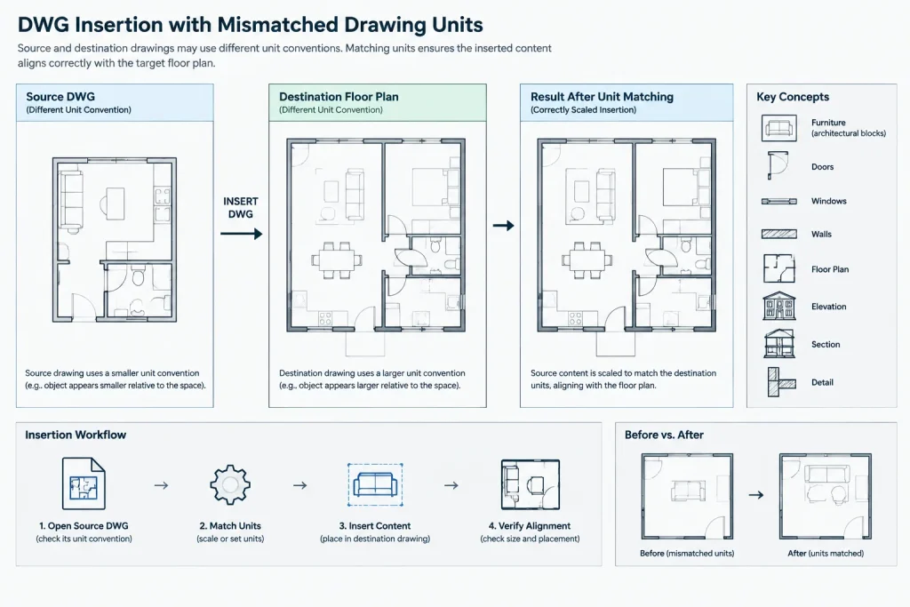
Architectural CAD drawings are generally modeled at full size, but a drawing unit does not always carry the same meaning from one file to another. One office may treat a drawing unit as an inch, another may use a millimeter, and an older library file may have no dependable unit assignment at all.
When a block or external drawing is inserted, CAD software may use the source and destination unit settings to calculate a conversion. If those settings do not describe the actual geometry, the resulting scale will be wrong even though the insertion process appears normal.
Common causes include:
- The source DWG and project DWG use different unit conventions.
- The source file’s unit setting does not match the way its geometry was drawn.
- A unitless legacy block depends on a manual insertion convention.
- The geometry was drafted at a plotted size instead of full model size.
- A block definition contains another block with its own scale.
- An existing definition with the same name is already loaded in the project.
- The object is an annotation symbol intended to maintain a printed size.
- An instance has been scaled without correcting the underlying definition.
Start with a Known Reference
Do not judge scale only by appearance. Open the source file separately and measure a feature whose real size can be verified. Suitable references include a scheduled door leaf, a manufacturer-documented fixture, a cabinet module, or another clearly identifiable component.
Avoid using an unfamiliar decorative object as the reference. A chair, plant, or sofa may plausibly exist in many sizes, so it cannot establish whether the file uses the correct units. The best reference is a feature connected to verified project information, a product document, or an explicit dimension in the source drawing.
Ask three questions:
- Is the measured geometry internally consistent?
- Does the drawing’s assigned unit match the apparent unit of the geometry?
- Is the object supposed to represent full-size construction or paper-size annotation?
This separates a unit mismatch from geometry that was simply drawn incorrectly.
A Practical Diagnostic Workflow
1. Inspect the destination drawing
Confirm the project drawing’s model-unit convention before changing the imported content. Review the drawing settings and measure a trusted project object. A written office standard, project setup note, or verified dimension is more dependable than assumptions based on the title block.
Do not change the units of an active project merely to accommodate one block. Such a change can affect later insertions and external references while leaving existing geometry unchanged, creating a more confusing file.
2. Open the source DWG independently
Opening the block file by itself makes it easier to inspect its extents, units, layers, and geometry. Measure a known feature and look for distant stray objects that may make the drawing appear unusually large when zooming to extents.
If the block arrived as a definition inside another drawing, use the block editor or create a controlled copy for investigation. Preserve the original file so that every correction can be traced or reversed.
3. Compare assigned units with actual geometry
The assigned unit is metadata; it does not prove that the geometry was drawn according to that unit. A file can report one convention while its dimensions clearly correspond to another. Resolve the contradiction using verified real-world information rather than trusting the setting alone.
If the geometry is correct but the metadata is wrong, correct the source file’s unit assignment through an approved office workflow. If the geometry itself is wrong, scale the source geometry using a known reference and then verify it again.
4. Test in a blank drawing
Insert the source into a blank test drawing configured like the project. A test file removes existing block definitions, project overrides, and unrelated content from the diagnosis. If the block works in the test file but not in the project, the problem likely lies in the destination drawing.
5. Check for a name conflict
When a drawing already contains a block with the same name, inserting another file may reuse the loaded definition rather than produce the expected geometry. This can make a corrected library block appear unchanged.
Compare the existing definition with the source. If a redefinition is appropriate, follow a controlled replacement process and review every affected instance. Redefining a block can update many locations at once, which is useful only when those locations are meant to share the same definition.
6. Inspect instance scale and nested content
Select the inserted block and review its scale properties. Uniform scaling changes all axes together, while nonuniform scaling can distort circles, doors, furniture, and symbols. Nonuniform values may also signal that someone stretched the block visually instead of repairing it.
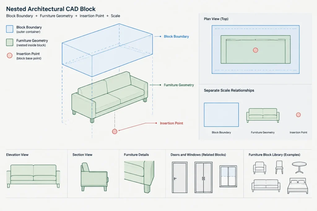
Open the definition and check for nested blocks. The outer reference may have a normal scale while an inner component carries an unexpected scale. Continue inspecting until the actual geometry is reached.
Choose the Correct Type of Fix
| Observed condition | Likely issue | Preferred response |
|---|---|---|
| All source geometry is consistently wrong by the same relationship | Unit convention or source scaling mismatch | Correct the source in a controlled copy and verify a known reference |
| Only one inserted instance is wrong | Instance scale was changed | Restore the intended scale after confirming the definition is correct |
| Corrected source still appears wrong in the project | Existing block definition or name conflict | Review and deliberately redefine or rename the block |
| Outer block is correct but parts are wrong | Nested block scaling | Repair the nested definition rather than compensating at the outer level |
| Symbol size relates to plotting rather than construction | Annotation behavior | Manage it as an annotation object under the project’s annotation system |
| Object looks stretched in one direction | Nonuniform scaling | Replace or repair the definition using undistorted geometry |
Model Components and Annotation Symbols Need Different Treatment
A toilet, desk, window, or appliance typically represents a full-size physical object in model space. Its size should be checked against verified product or project information. A north arrow, section marker, room tag, or similar symbol is different because its graphic size is often governed by sheet readability.
Do not enlarge an annotation symbol as if it were a building component, and do not shrink model geometry merely because it looks large in a viewport. First determine whether the content belongs to the model, the annotation system, or the sheet.
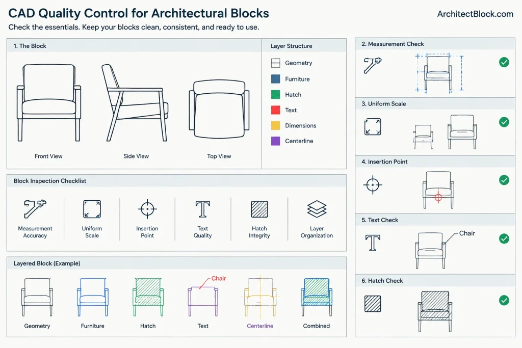
Some blocks combine both categories, such as a fixture outline with an identification label. These blocks need special care because scaling the entire definition may correct one part while damaging the other. Separating model geometry from annotation may provide a more maintainable solution.
Blocks Versus External References
Blocks and external references can show similar unit problems, but their management differs. A block definition becomes part of the destination drawing. An external reference remains linked to another file and may be reloaded as that file changes.
Before scaling an external reference manually, verify the unit convention at the source and destination. A manual override can make the current view look correct while leaving the underlying coordination problem unresolved. This is especially risky when consultant backgrounds are updated later.
Quality Checks After Correction
After repairing an incorrectly scaled CAD block, complete more than a visual review:
- Measure at least one verified feature.
- Confirm the block scale is intentional and preferably uniform.
- Check rotation and insertion point behavior.
- Review nested blocks, attributes, text, and hatch patterns.
- Test the block at the intended viewport and plot scale.
- Confirm that linework remains readable and is assigned to appropriate layers.
- Search for other instances that may have inherited the same problem.
- Record the correction in the library or project quality-control notes.
If the object came from an outside source, keep the unedited original and save the cleaned version under a controlled library name. This prevents uncertainty about whether a future copy has been reviewed.
Avoid the “Scale Until It Looks Right” Method
Visual scaling may be acceptable for a noncritical presentation object when exact size is irrelevant, but it should not be the default for architectural components. A block that merely looks plausible can interfere with clearances, room layouts, elevations, schedules, and consultant coordination.
The durable solution is to establish the intended real-world size, verify the unit convention, repair the correct level of the block structure, and test the result in a controlled drawing. That process takes longer than an arbitrary scale adjustment, but it produces reusable DWG content that behaves consistently across the project and the wider CAD library.
Decide Where the Correction Belongs
A lasting repair should be made at the level where the error originates. If verified source geometry is correct, investigate insertion behavior and destination-drawing definitions before editing the block. If the geometry is incorrect in its own file, changing individual project instances only hides the source problem.
Use a controlled library copy when a correction could affect other drawings. A project-specific adjustment may be appropriate when the source must remain unchanged, but the reason for that adjustment should be documented so another drafter does not mistake it for the standard block.
Build a Repeatable CAD Quality-Control Habit
Scale verification is most effective when it becomes part of the content-review process. Before adding an outside block to a shared library, inspect its geometry, insertion point, layers, attributes, nested content, and intended role as either model geometry or annotation.
- Verify before placement: Measure a recognizable feature against dependable project or product information.
- Separate diagnosis from correction: Determine whether the issue belongs to the source file, destination file, definition, or individual reference.
- Protect reviewed content: Retain the original file and identify the cleaned library version clearly.
- Test reuse: Insert the corrected content into a controlled drawing to confirm that the repair is not dependent on one project file.
- Document exceptions: Record intentional scaling, annotation behavior, or project-specific handling.
This approach reduces repeated troubleshooting and makes architectural CAD libraries easier to audit, update, and share.
Frequently Asked Questions
Why does a CAD block remain the wrong size after I correct the source file?
The destination drawing may already contain a block definition with the same name. It may continue using that stored definition until the block is deliberately redefined, renamed, or otherwise managed through the project workflow.
Should I change the project drawing units to fix one block?
Usually, the block should be diagnosed independently first. Changing an active project’s unit settings to accommodate isolated content can create inconsistent behavior for later insertions and referenced files.
How can I tell whether the unit setting or the geometry is wrong?
Measure a feature with a verified real-world size and compare that result with the source file’s assigned unit convention. The setting is metadata; the measured geometry reveals how the content was actually drawn.
Why is only part of a block incorrectly scaled?
The definition may contain nested blocks, annotation, text, attributes, or imported components with separate scaling behavior. Inspect the block hierarchy until you reach the affected geometry rather than compensating at the outer reference.
Is nonuniform scaling acceptable for architectural blocks?
Nonuniform scaling can distort geometry and should be treated cautiously. If it was used to make an object fit visually, replacing or repairing the underlying definition generally produces more dependable content.
Can annotation symbols be checked like furniture or fixtures?
Not in the same way. Furniture and fixtures generally represent physical model objects, while annotation symbols are often controlled for sheet readability. Identify the content type before deciding how its size should be managed.