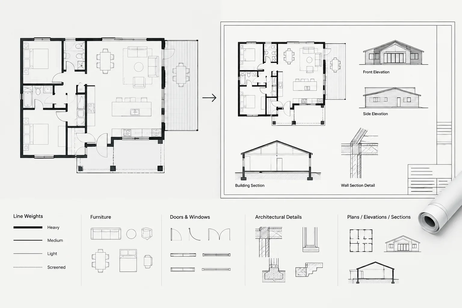
Choosing between CTB and STB plot styles is ultimately a workflow decision. Either system can create a clear architectural drawing set, but unreliable results appear when layer properties, object overrides, page setups, referenced files, and plot tables follow different conventions.
This guide explains how each system controls output, where coordination problems commonly occur, and how to maintain a repeatable plotting process. Use it when establishing a template, reviewing a consultant file, cleaning imported CAD content, or diagnosing a sheet that does not plot as expected.
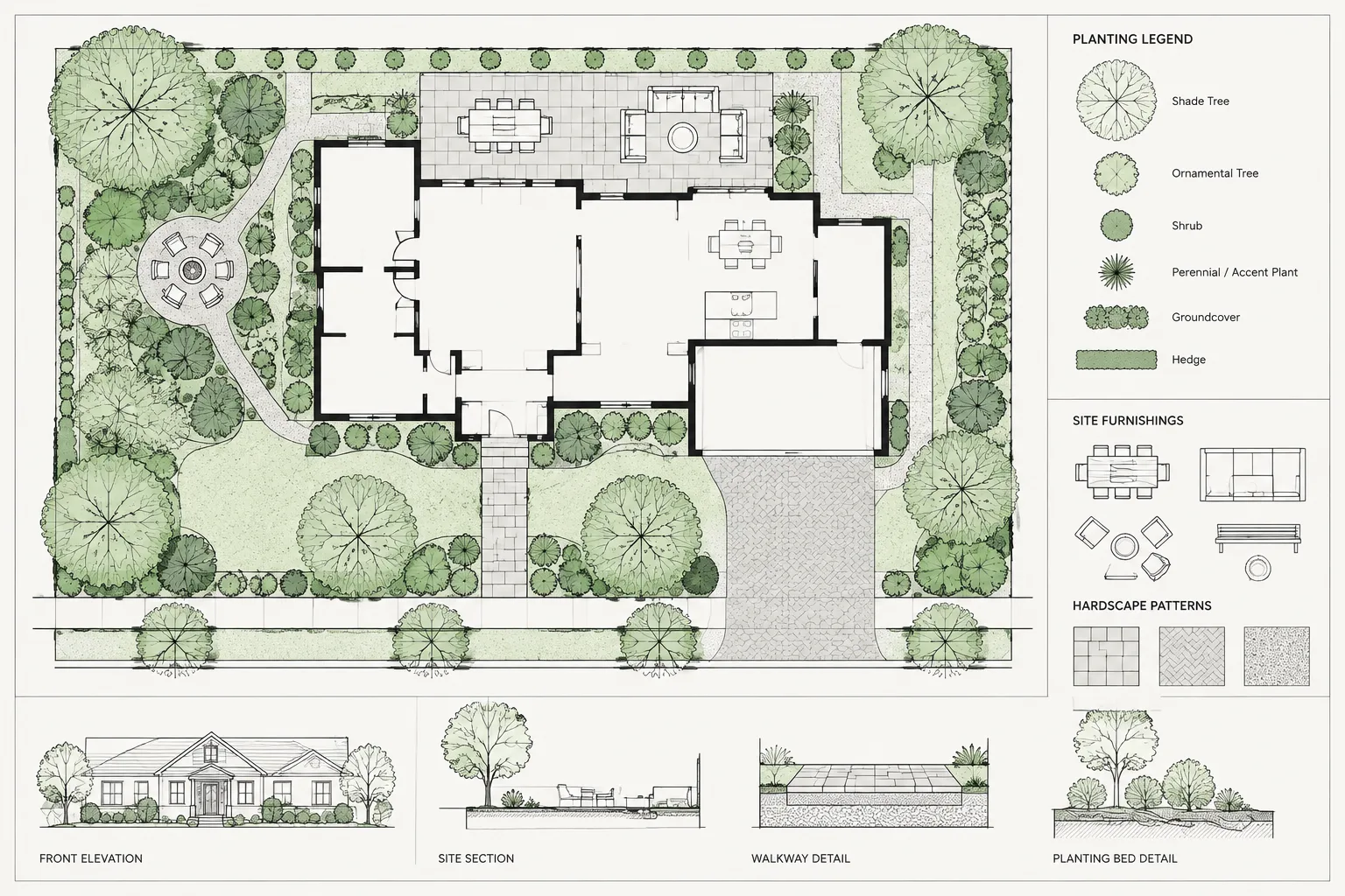
Clear architectural drawings depend on more than accurate geometry. Walls, fixtures, annotations, hatches, and background information must also plot with a readable visual hierarchy. In AutoCAD-based workflows, that hierarchy is often controlled partly through plot style tables.
The two plot style systems are color-dependent plot styles, commonly stored in CTB files, and named plot styles, commonly stored in STB files. Both can produce professional drawing sets. The important issue is not which system is universally better, but whether the drawing, template, layers, page setups, and office standards all use the same logic.
What a plot style controls
A plot style changes how drawing information is sent to a printer, plotter, or digital output. Depending on the table and page setup, it may affect plotted color, lineweight, screening, linetype, and other output properties.
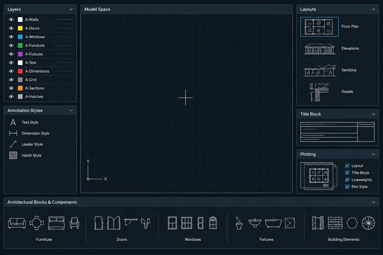
Plot styles should be treated as one part of the drawing hierarchy rather than a substitute for good layer management. A reliable architectural file usually coordinates several related controls:
- Layers organize elements by purpose and drawing discipline.
- Object properties determine color, linetype, and lineweight behavior.
- Plot styles translate those properties into printed output.
- Page setups select the output device, paper configuration, plot area, scale, and plot style table.
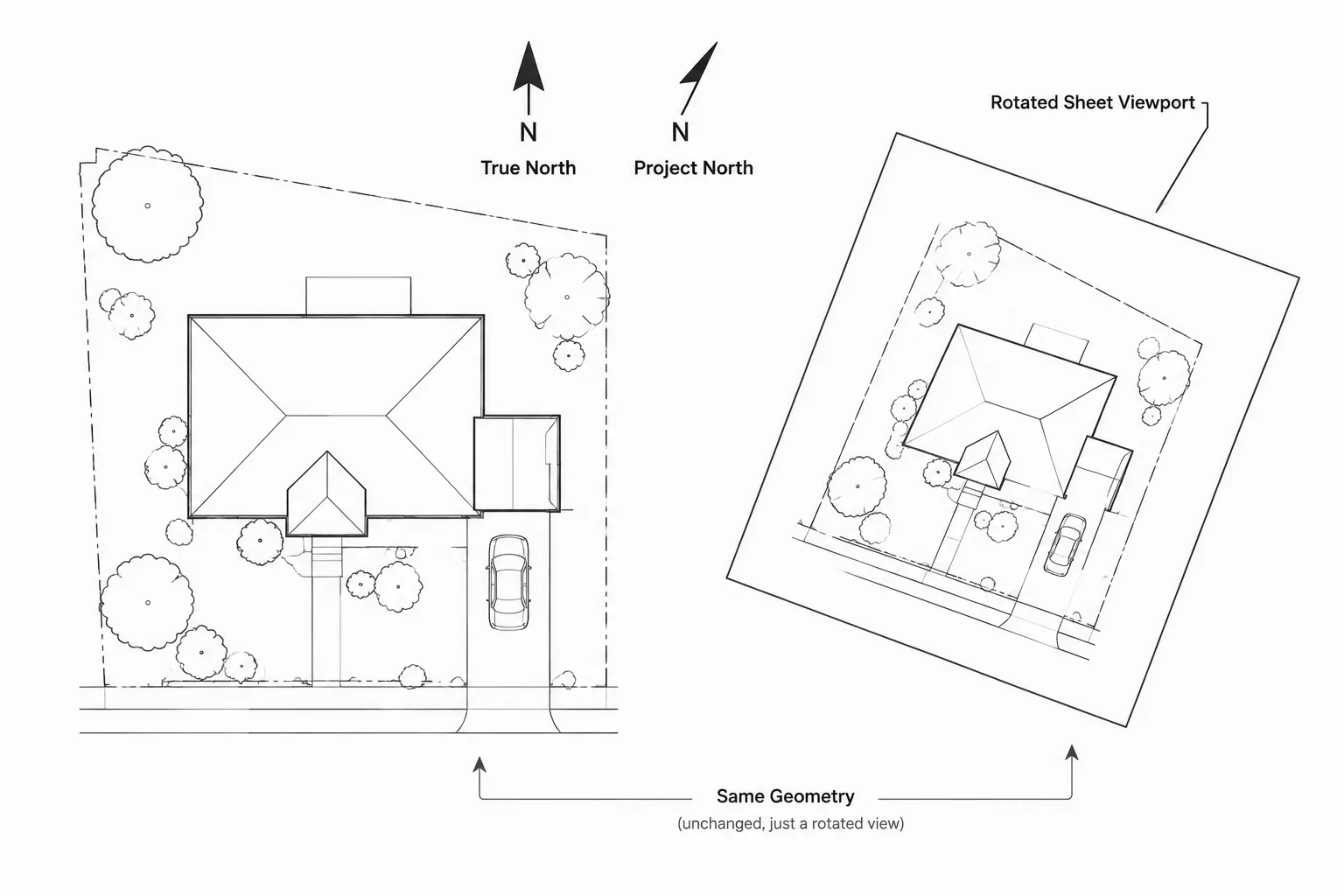
- Layout viewports control the displayed scale and may apply viewport-specific layer overrides when needed.
Confusion begins when these controls compete. For example, a wall may have a layer lineweight, an object-level lineweight override, and a plot style that assigns another lineweight. Establishing one primary method reduces troubleshooting.
How CTB color-dependent plot styles work
A CTB workflow assigns plotting behavior according to an object’s indexed color. In a common architectural setup, layers are given specific indexed colors, and each color corresponds to a plotted lineweight or screening value.
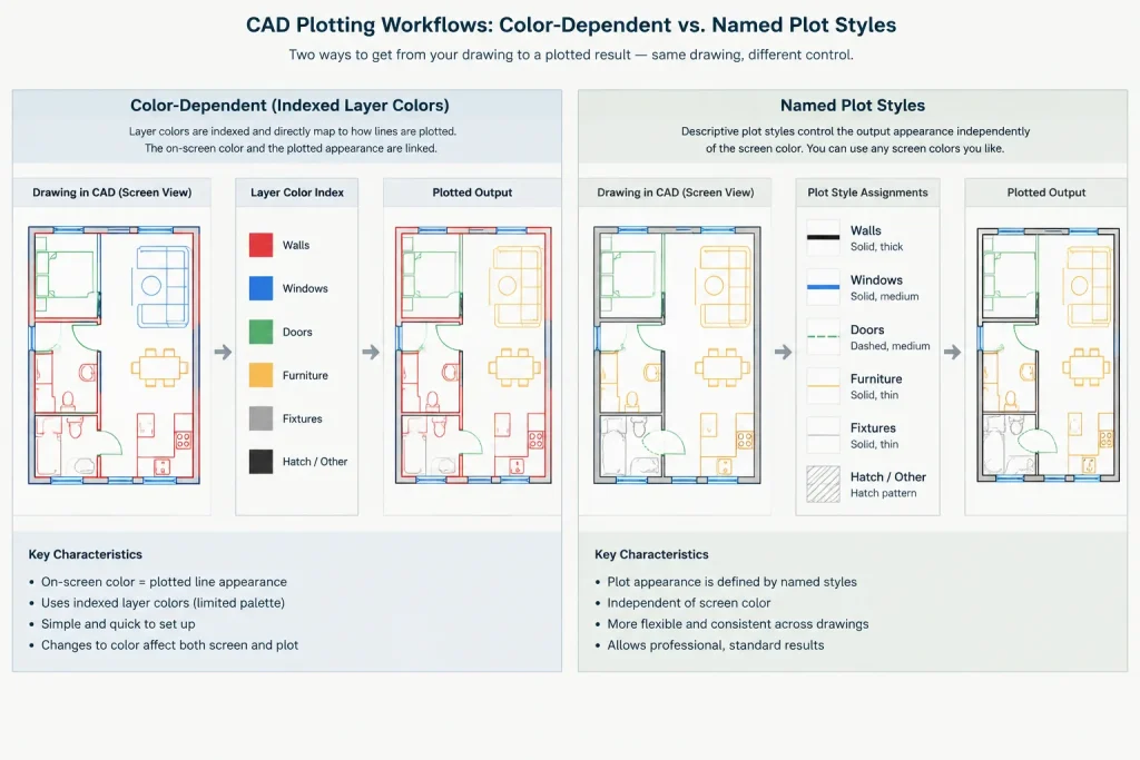
This creates a compact visual drafting language. A user may recognize that one layer color represents a heavy cut line while another represents a light surface line. On screen, those colors help distinguish drawing categories even when the final sheets plot in black or grayscale.
Advantages of a CTB workflow
- It is familiar in many architectural and consultant environments.
- Layer colors provide immediate visual clues about intended plotted weight.
- A small, controlled color palette can produce a consistent hierarchy.
- It works well with established office templates and legacy DWG libraries.
Limitations of a CTB workflow
- Color is doing two jobs: screen identification and plot control.
- Changing an object’s color may unintentionally change its plotted appearance.
- Downloaded blocks can introduce colors that do not match the office table.
- True-color or other nonstandard color use should be tested because it may not follow the expected indexed-color mapping.
- A missing CTB file can make a drawing plot very differently from its intended appearance.
CTB systems are most dependable when objects use ByLayer properties and the layer palette is disciplined. Random object colors and nested block overrides make the relationship between the screen display and final plot harder to predict.
How STB named plot styles work
An STB workflow uses named styles rather than relying on indexed color as the main plotting key. Names can describe graphic intent, such as a heavier profile, a standard object line, a light background, or screened reference information. The exact names should come from the project or office standard.
Because color and plot style are separate, layers can use colors for screen organization while named styles determine output. This can make the plotting logic easier to explain: the style name communicates what the element should look like on the sheet.
Advantages of an STB workflow
- Plotting intent can be expressed with descriptive style names.
- Screen color does not have to determine plotted lineweight.
- Users can organize layers visually without automatically changing print hierarchy.
- Named styles can support a direct relationship between graphic purpose and output.
Limitations of an STB workflow
- Users familiar only with CTB files may not know where the output behavior is assigned.
- Imported objects can carry unexpected named styles or default assignments.
- The system requires consistent style naming and careful template setup.
- Sending only the DWG without its required STB table can produce incorrect output.
CTB and STB compared
| Workflow question | CTB | STB |
|---|---|---|
| What primarily selects the plot style? | Indexed object or layer color | Assigned plot style name |
| Can screen color be independent of plotting intent? | Only within the limits of the color-based system | Yes, color and named style can be managed separately |
| What should users inspect first? | Layer and object colors | Named plot style assignments |
| What must accompany shared files? | The required CTB file and page setup information | The required STB file and page setup information |
| Best reason to use it | Compatibility with an established color-based standard | Clear separation of screen color and plotting purpose |
Choose the system before production drafting
Plot style mode is a drawing-level decision. Start new work from a verified project template instead of opening an arbitrary file and adding layers. The template should already contain the intended plot style system, core layers, text and dimension styles, layouts, and page setups.
When collaborating, do not choose CTB or STB according to personal preference. Confirm the project’s required format before creating production drawings. Architectural backgrounds, consultant files, and sheet files should use a coordinated approach or have a documented translation process.
Existing drawings can be converted between plot style systems, but conversion should not be treated as a cosmetic switch. Style assignments, layer behavior, blocks, and page setups may need review. Always work on a copy, create test output, and compare it with a known reference sheet before accepting the conversion.
Build a practical architectural plot hierarchy
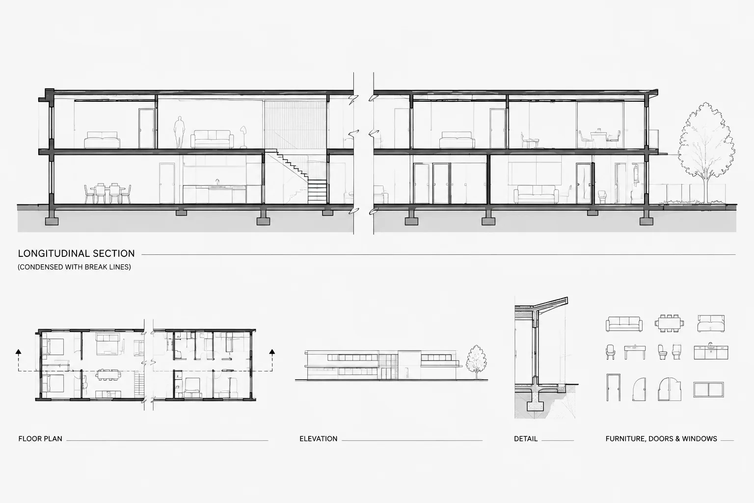
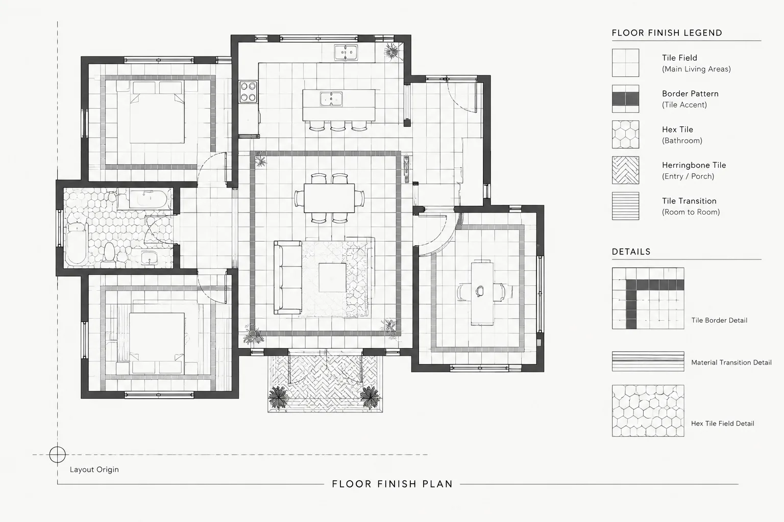
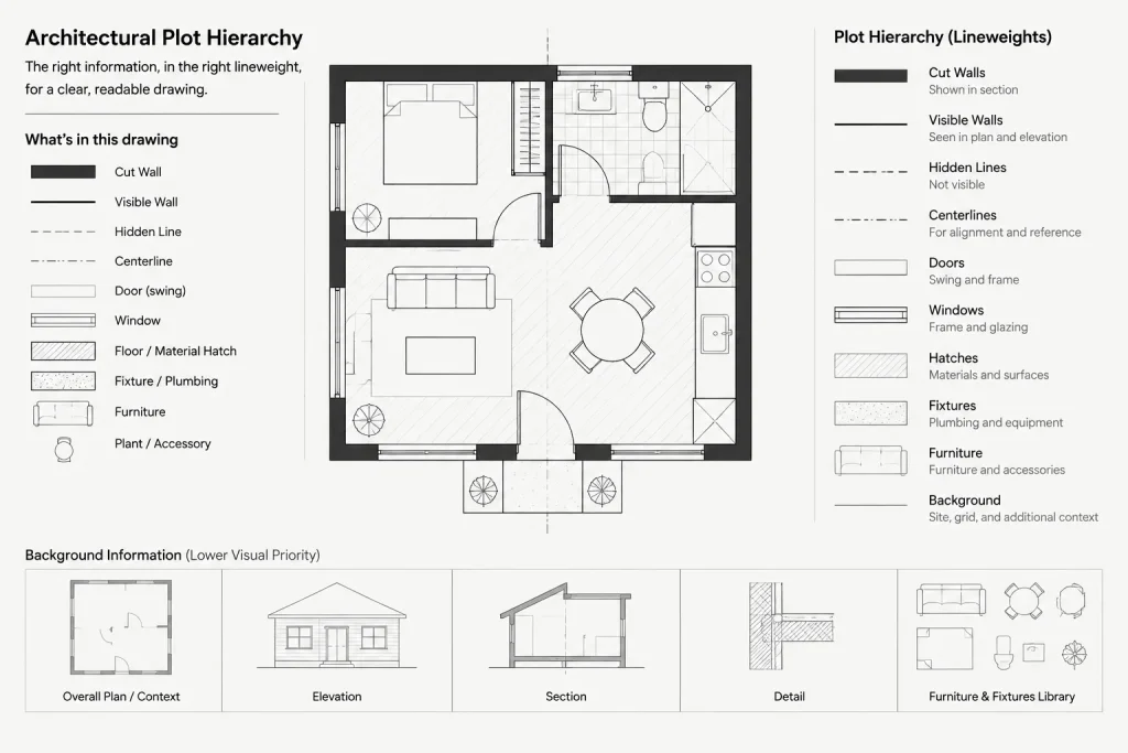
Begin with drawing roles rather than colors or style names. Typical graphic roles include cut elements, prominent outlines, secondary visible edges, overhead information, surface patterns, annotation, dimensions, and background references. The project team can then assign appropriate lineweights and screening behavior according to its own standard.
Avoid creating a different plot style for every object category. Doors, casework, plumbing fixtures, and furniture may belong on different layers, but several categories can share the same plotted hierarchy when they have the same visual role.
Likewise, do not rely on screening to repair an overcrowded drawing. First determine whether the information belongs in that view. Screening is useful for contextual or secondary information, but it does not replace careful selection, clipping, layer control, or annotation placement.
Coordinate plot styles with blocks and external references
Downloaded CAD blocks often contain object-level colors, lineweights, or nested layers. In a CTB drawing, those colors may map to unintended weights. In an STB drawing, imported objects may use an unexpected named style or inherit a default style that does not match their role.
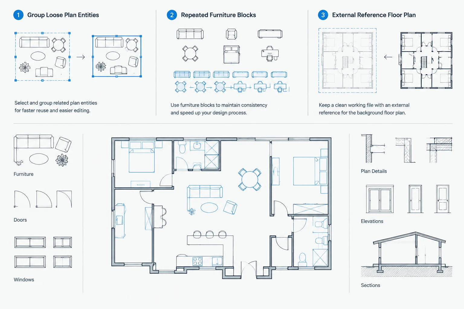
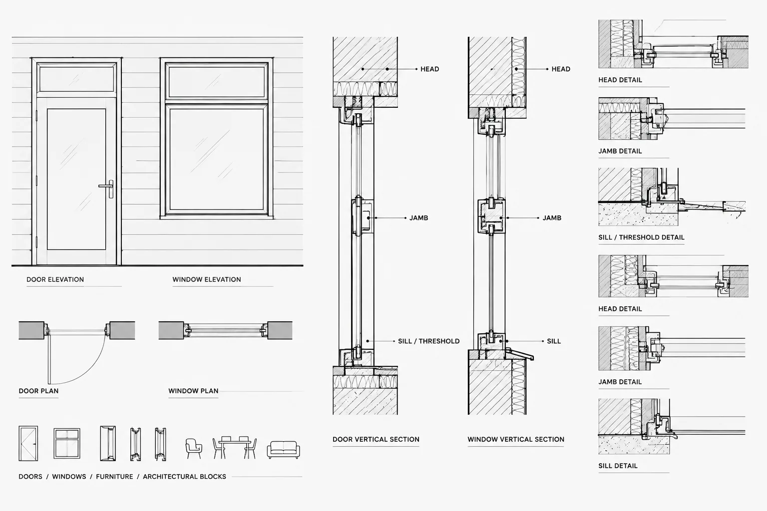
Before placing a block in the project library, inspect its geometry in a clean working file. Move elements to appropriate layers, remove unnecessary property overrides, and confirm that nested content behaves correctly. Where practical, use ByLayer properties so the host drawing controls appearance.
External references require similar care. A referenced consultant background may need to remain distinguishable from the architectural work without permanently editing the source file. Layer overrides within the architectural sheet file can help manage visibility and plotted emphasis, but they should be documented and checked whenever the reference is updated.
Troubleshooting inconsistent output
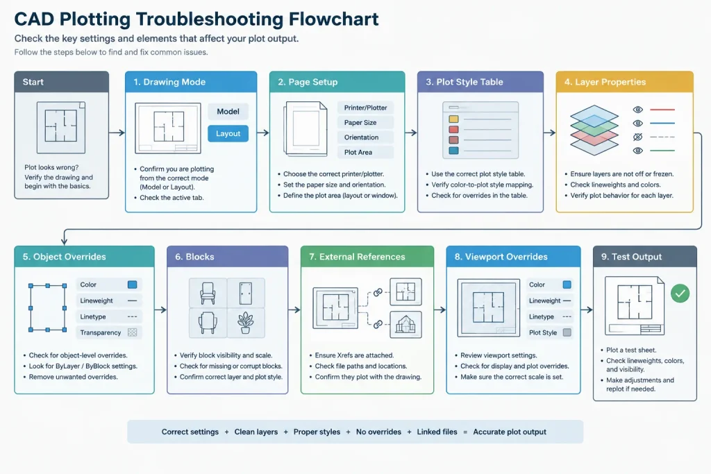
When a sheet looks correct on screen but plots incorrectly, check the workflow in a fixed order:
- Confirm whether the drawing uses CTB or STB plot styles.
- Verify that the intended plot style table is available and selected in the page setup.
- Check whether plot styles are enabled for the output.
- Inspect the affected object’s layer, color, lineweight, and plot style properties.
- Look for object-level overrides inside blocks.
- Review viewport-specific layer overrides in the layout.
- Check whether an external reference introduced different property conventions.
- Produce a test PDF or print and evaluate the actual output rather than relying only on the model-space display.
If only one object plots incorrectly, the problem is likely local to that object, block, or layer. If the entire sheet is wrong, inspect the page setup and plot style table first. If several sheets are inconsistent, compare their layouts and page setups instead of editing geometry.
Create a plot test sheet
A compact test sheet is one of the most useful quality-control tools for either system. It can display the colors or named styles used by the office alongside representative lines, text, hatches, dimensions, and screened elements. Plot it using the same page setup as the production sheets.
Review the test on the intended output medium. Fine distinctions that appear clear in a PDF viewer may be less obvious on paper, and printer behavior can vary. The goal is not to create the greatest possible number of weights. It is to produce a simple, repeatable hierarchy that remains readable at the sheet’s plotted scale.
Maintain the system as a project resource
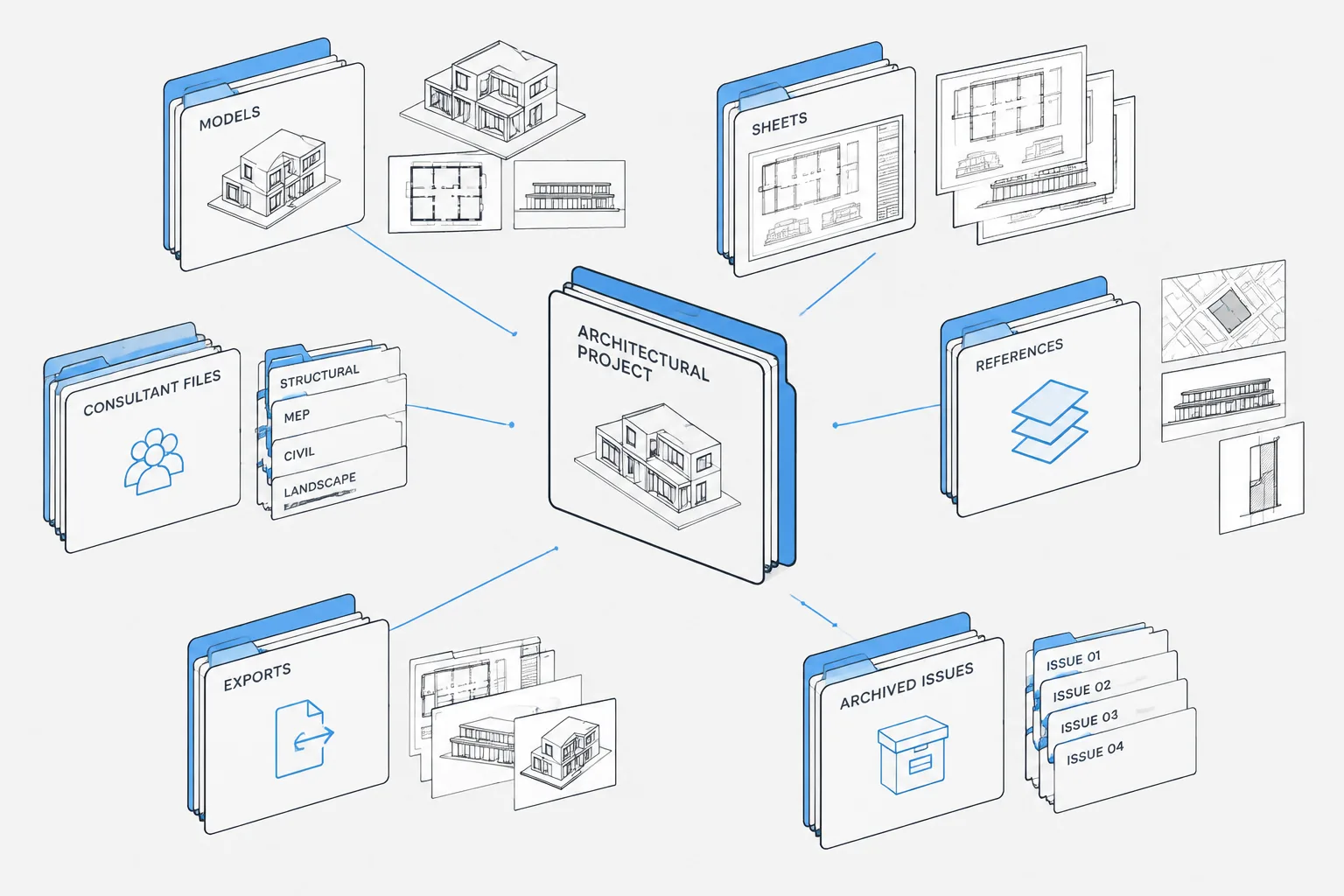
Keep required CTB or STB files with the project’s controlled support resources, and identify which table each sheet series uses. Coordinate page setups through approved templates rather than rebuilding them manually in every layout.
Before issuing or archiving a drawing set, verify that another team member can open the files and reproduce the expected output. A well-designed plot style system is successful only when it remains understandable, portable, and consistent across the complete architectural drawing set.
A practical decision test for project teams
Before selecting a plot style system, identify the standard already governing the project. If established templates, consultant backgrounds, sheet files, and support resources use color-dependent plotting, retaining CTB will usually reduce translation work. If the project is intentionally organized around named graphic roles, STB may provide a clearer separation between screen color and plotted appearance.
The decision should be applied consistently rather than made layout by layout. Mixing assumptions can make drawings difficult to review because the same color, layer, or object property may produce different output in different files.
Plot-style handoff checklist
A reliable handoff includes more than the DWG file. Before transferring, issuing, or archiving project drawings, review the complete plotting environment:
- Confirm that every production file uses the intended CTB or STB system.
- Include the required plot style table within the controlled project resources.
- Verify that approved page setups reference the correct table.
- Check that layer, object, block, and viewport overrides are intentional.
- Review external references for conflicting color or named-style conventions.
- Create output from representative layouts and compare the graphic hierarchy across the set.
- Ask another team member to reproduce the output using the transferred resources.
Separate drafting organization from plotted emphasis
Layers answer what an element is and how it should be managed. Plot styles help determine how that element is emphasized in output. Keeping those purposes distinct makes a file easier to edit, audit, and exchange.
For example, several object categories may require separate layers for visibility control while sharing the same plotted emphasis. Conversely, objects on related layers may need different treatment because one is cut, another is seen beyond, and another is only contextual. Build the hierarchy around drawing meaning rather than assigning a unique plotted appearance to every layer.
Use plotted output as the final quality check
Model-space colors and on-screen line displays are useful drafting aids, but they are not the final measure of sheet clarity. Review actual output at the intended sheet scale and medium. Check whether cut elements, visible edges, annotations, hatches, and reference information remain distinguishable without overwhelming one another.
If a correction is needed, identify the controlling level before editing. A local problem may come from an object override or nested block. A viewport-specific problem may come from a layout override. A sheet-wide problem is more likely connected to the page setup or selected plot table. This diagnostic approach avoids unnecessary changes to otherwise correct geometry.
Frequently asked questions
Can a drawing use both CTB and STB plot styles at the same time?
The drawing operates within one plot style mode. Files from different systems can be exchanged or converted, but their plotting logic must be reviewed rather than assumed to transfer automatically.
Why is the expected CTB file missing from the plot settings?
First confirm that the drawing is using the color-dependent plot style system. Also verify that the required support file is available in the configured plotting environment. A named-style drawing will not present plotting choices in the same way as a color-dependent drawing.
Why does changing an object color alter its plotted lineweight?
In a CTB workflow, indexed color commonly selects the plotted behavior. Changing the object or layer color can therefore select a different entry in the plot table. Check whether the object should inherit its color from the layer before applying an override.
Why does an imported CAD block plot too heavily or too lightly?
The block may contain nested objects with fixed colors, lineweights, layers, or named plot styles. Inspect the original block definition in a controlled working file, remove unnecessary overrides, and align its properties with the host drawing standard.
Should plot style problems be fixed by editing every object?
Not usually. Determine whether the problem affects one object, one viewport, one layout, or the complete sheet set. The appropriate correction may belong in the block definition, layer properties, viewport overrides, page setup, or plot style table.
What should be sent with a DWG for reproducible plotting?
Provide the required CTB or STB resource and enough page-setup information for the recipient to reproduce the intended output. Referenced drawings, fonts, and other project support resources should also follow the established handoff process.