
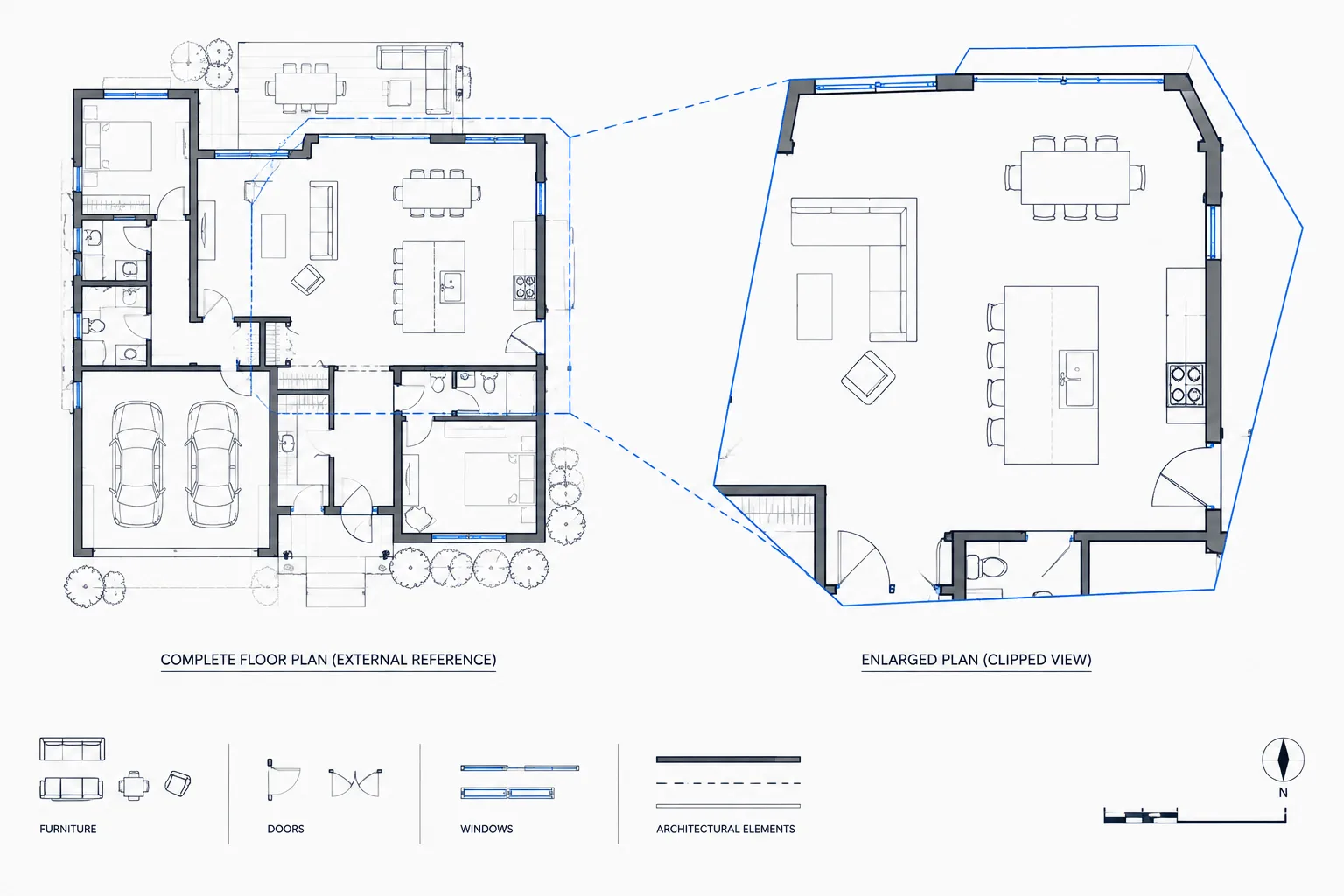
Clipping external references in architectural CAD helps isolate the portion of a coordinated DWG needed for a particular plan, elevation, section, or detail. Used carefully, an Xclip boundary can reduce visual clutter without altering the referenced source geometry.
This guide explains where xref clipping fits within a broader drawing workflow, how it differs from layer and viewport control, and what to review before plotting or handing the file to another CAD user.
Architectural drawings often need only part of an externally referenced DWG. An enlarged restroom plan may require a small portion of the floor plan, while a building elevation may need only the relevant section of a larger site background. Clipping the external reference can hide unrelated geometry without modifying the source file.
This is especially useful when the same coordinated background supports several drawings at different scales. However, clipping should be treated as a display and drawing-organization tool—not as a substitute for properly organized source files, layers, or viewports. A reliable workflow keeps the boundary understandable, preserves coordination context, and makes hidden geometry easy to recover.
What an xref clipping boundary does
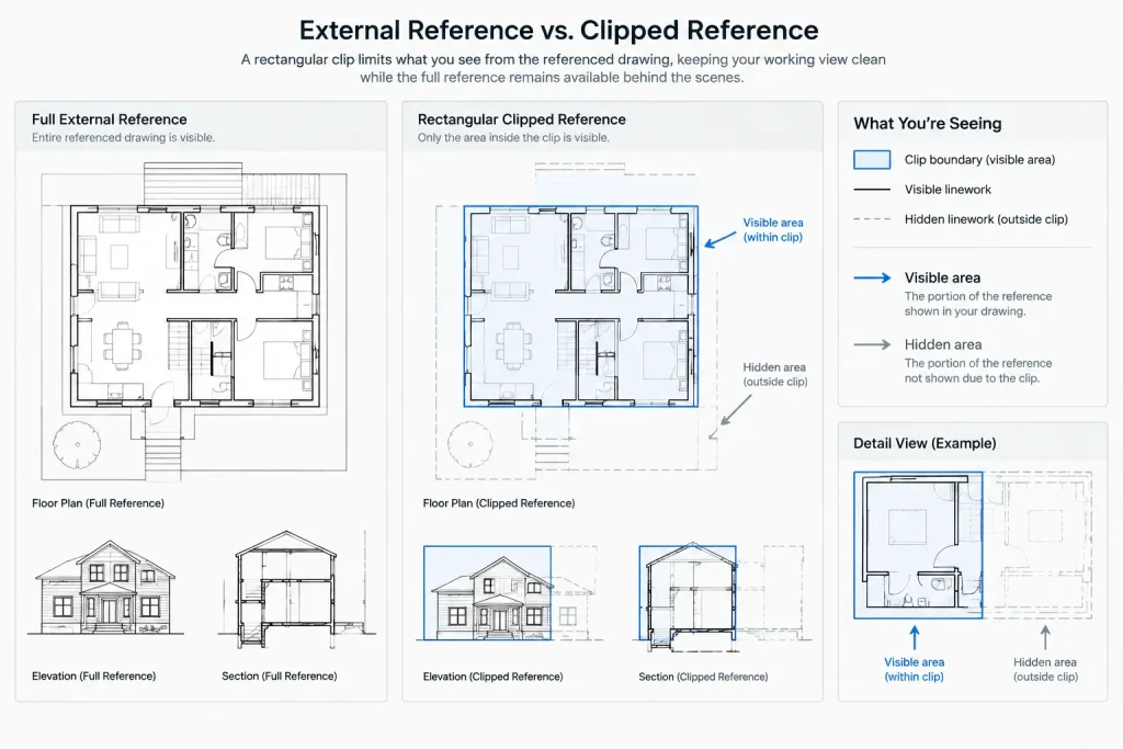
An external reference clipping boundary limits which portion of an attached or overlaid DWG is visible in the host drawing. Geometry outside the selected boundary is hidden from view, but it remains in the referenced source file. Removing or disabling the boundary restores the full reference display.
In AutoCAD-based workflows, this is commonly managed with the XCLIP command. The clip belongs to the selected reference instance in the host drawing. It does not erase objects from the referenced DWG and does not create a cropped copy of the source file.
This distinction matters when coordinating drawings. A clipped floor plan may look incomplete in the host file even though the source model contains the entire building. Team members should be able to recognize that geometry is hidden by a boundary rather than missing from the source.
When clipping external references is useful
- Enlarged plans: Isolate a restroom, kitchen, stair, lobby, or other focused area from a complete floor-plan background.
- Partial floor plans: Display one wing, tenant area, or drawing zone while retaining the coordinated master plan as the source.
- Interior elevations: Limit the floor-plan reference to the room or wall area needed for projection and checking.
- Building sections: Reduce distant plan geometry that does not contribute to the section being developed.
- Site and floor-plan coordination: Show only the building vicinity needed for an architectural plan without editing the civil or survey background.
- Composite drawings: Combine selected portions of several references while controlling visual overlap.
Clipping is less appropriate when unwanted objects can be managed more clearly through layers or when the same geometry should be hidden in every use of the source file. In those situations, improving the source drawing or its layer structure may produce a more maintainable result.
Clipping, layer control, and viewport cropping are different
| Method | What it controls | Typical architectural use |
|---|---|---|
| Xref clipping | The visible area of a selected reference instance | Showing only part of a referenced floor plan in an enlarged drawing |
| Layer visibility | Object categories within the referenced drawing | Hiding furniture, annotation, ceilings, or other organized content |
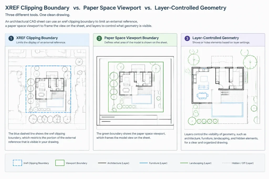
| Viewport boundary | The paper-space window through which model space is shown | Composing a view on a drawing sheet |
| Source-file editing | The actual geometry and organization of the referenced DWG | Correcting errors or making changes that should appear wherever the source is referenced |
These methods can work together. For example, a viewport may frame an enlarged plan, an xref clip may limit the background to the work area, and layer controls may suppress categories that are not relevant to that view.
A practical xref clipping workflow
Start with a coordinated reference
Confirm that the external reference is correctly located, oriented, and scaled before clipping it. A boundary created around a misplaced background can make the view appear correct temporarily while concealing an underlying coordination problem.
Review the reference path and identify whether it is attached or overlaid according to the project’s xref strategy. Also check for nested references. A nested file may remain visible, disappear with its parent, or create unexpected overlap depending on how the reference structure is assembled.
Define the actual drawing area
Determine what the finished view must communicate before drawing the boundary. Include enough surrounding information to establish orientation and relationships. An enlarged room plan may still need adjacent walls, corridor edges, grid references, door approaches, or section markers.
A boundary that follows every wall recess can be unnecessarily difficult to edit. Use the simplest shape that presents the required content. Rectangular boundaries work well for many enlarged plans, while polygonal boundaries can fit irregular wings, angled buildings, or selective composite views.
Create the clipping boundary
Select the intended external reference and start the clipping command. Define a new rectangular or polygonal boundary, or use a suitable closed polyline where supported by the workflow. Avoid snapping to temporary annotation or objects likely to move independently of the architectural area.
If the boundary must track a logical division, base it on stable references such as grid relationships, primary wall extents, or an established match-line location. After creating the clip, zoom out and confirm that the correct side of the boundary remains visible.
Control boundary visibility
Clipping frames are useful during editing because they reveal why parts of a reference are hidden. In plotted output, however, the frame may be unwanted. Manage frame display and plotting according to the office’s CAD setup, and verify the result in a test plot or exported PDF.
Do not rely only on the fact that a frame appears faint or unobtrusive on screen. Screen appearance, plot configuration, and final output can differ.
Annotate after the background is stable
Place dimensions, room tags, keynotes, and callouts only after verifying the clipped background. Associating annotation with geometry near a clip edge deserves particular attention. If the boundary later changes, an annotation object may remain even when the referenced object it describes is no longer visible.
Keep host-drawing annotation separate from reference geometry through clear layer organization. This makes it easier to inspect, freeze, plot, and revise each information type.
How to manage several clips from one source
A single source DWG can be referenced more than once in the same host drawing. Each instance can have a different clip, layer state, display treatment, or purpose. This can support multiple enlarged areas without creating cropped copies of the source file.
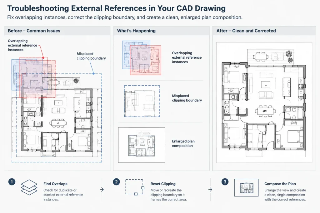
Repeated instances should remain easy to identify. Use descriptive xref instance names where the software and office workflow permit, and keep a clear relationship between each clipped background and its drawing view. Avoid stacking duplicate references without documenting why they exist; overlapping instances can produce heavy linework, confusing selection behavior, and inconsistent layer overrides.
Before moving a clipped reference, confirm whether the intent is to relocate the entire background or merely revise the clipping boundary. Moving the reference changes its coordinate relationship to the host drawing. Editing the boundary changes only the displayed area.
Common clipping problems and what to check
Expected objects are missing
- Temporarily display or select the clipping boundary to confirm its location.
- Check whether the boundary is showing the intended side.
- Review xref layer visibility and overrides.
- Open the source file to verify that the objects actually exist there.
- Inspect nested references if the missing content comes from another attached file.
Geometry appears outside the intended area
Confirm that the visible object belongs to the clipped reference rather than a second reference, a block, or native geometry in the host drawing. Overlapping backgrounds are common in composite plans. Selecting the object or isolating candidate layers can help identify its source.
The frame appears in the final output
Review the clipping-frame display and plot settings, then create a test output. Also check whether a manually drawn polyline was left around the view. A construction boundary and an actual xref clipping frame are not necessarily the same object.
The clip no longer fits after a design revision
Source geometry can move beyond an existing boundary. Include clipping review in the update process when referenced plans change. Do not assume that reloading an xref automatically adjusts the host drawing’s clipping limits to follow revised rooms or walls.
Quality-control checklist
- Verify the reference insertion point, scale, rotation, and coordinate relationship.
- Confirm that the clip includes the context needed to understand the view.
- Check for duplicate or overlapping reference instances.
- Review nested xrefs and reference layer visibility.
- Inspect annotation near every clip edge.
- Confirm that required grids, datums, callouts, and match information remain visible.
- Test the drawing at its intended plot scale.
- Review the exported PDF for unwanted frames and missing linework.
- Make sure another CAD user can identify and edit the clipped reference without reconstructing the workflow.
Use clipping as a presentation tool, not a coordination shortcut
Clipping external references can make architectural DWG files cleaner and more focused while preserving a shared source background. Its strongest use is view-specific: isolating an enlarged area, removing distant geometry, or assembling a readable drawing from coordinated references.
The boundary should not conceal unresolved alignment, poor layer organization, or unnecessary content indefinitely. Keep the source drawing coordinated, use layer controls for object categories, use viewports for sheet composition, and use clipping only to define the portion of a reference needed for a particular architectural view. That separation produces files that are easier to review, revise, and hand off.
Choose the control that matches the drawing problem
Before creating or revising a clip, identify what actually needs to change. If an entire category of objects is unnecessary, layer visibility may be the clearer control. If the issue concerns sheet composition, adjust the viewport. If the underlying geometry is incorrect, revise the coordinated source through the project’s established process. Use an xref clipping boundary when the source is correct but only part of that reference should appear in a particular host-drawing view.
This distinction prevents a visually successful clip from masking a coordination issue. It also helps future editors understand whether missing information is intentionally hidden, turned off by layer, outside a viewport, or absent from the source.
Make clipped references easier to hand off
A maintainable clipped view should communicate its purpose without requiring another user to reverse-engineer the file. Keep reference instances identifiable, avoid unexplained duplicate backgrounds, and retain enough surrounding context to show where the displayed area belongs within the larger plan.
During revision review, compare the clip against the current reference rather than relying only on the previous plotted view. Changes to walls, rooms, circulation, grids, or annotation can make an existing boundary misleading even when the reference reloads correctly. The final check should include both the editable CAD view and the plotted or exported result.
Frequently asked questions about Xclip workflows
Does clipping an xref change the referenced DWG?
No. The boundary controls the displayed portion of the selected reference instance in the host drawing. It does not erase or crop the source geometry.
Should Xclip replace xref layer control?
No. Clipping controls the visible area of a reference, while layer controls manage object categories. A drawing may use both when the view requires a limited area and a reduced set of information.
What is the difference between an xref clip and a viewport boundary?
An xref clip limits a selected reference instance. A viewport boundary controls the model-space area seen through a paper-space view. They can be used together, but they solve different drawing-organization problems.
Why can referenced geometry disappear unexpectedly?
The object may fall outside the clipping boundary, be hidden by a layer setting, belong to a nested reference, or be absent from the current source file. Checking each of these conditions helps distinguish clipping from a coordination or visibility problem.
Can the same source DWG have different clipped areas?
Yes. Separate instances of the same source can use different clipping boundaries and display treatments. Each instance should have a clear purpose so overlapping references do not create confusing linework or selection behavior.
Should the clipping frame appear on the finished sheet?
That depends on the intended graphic result and the office CAD setup. Review frame display and plotting behavior, then inspect a test plot or exported file rather than relying only on the on-screen appearance.

