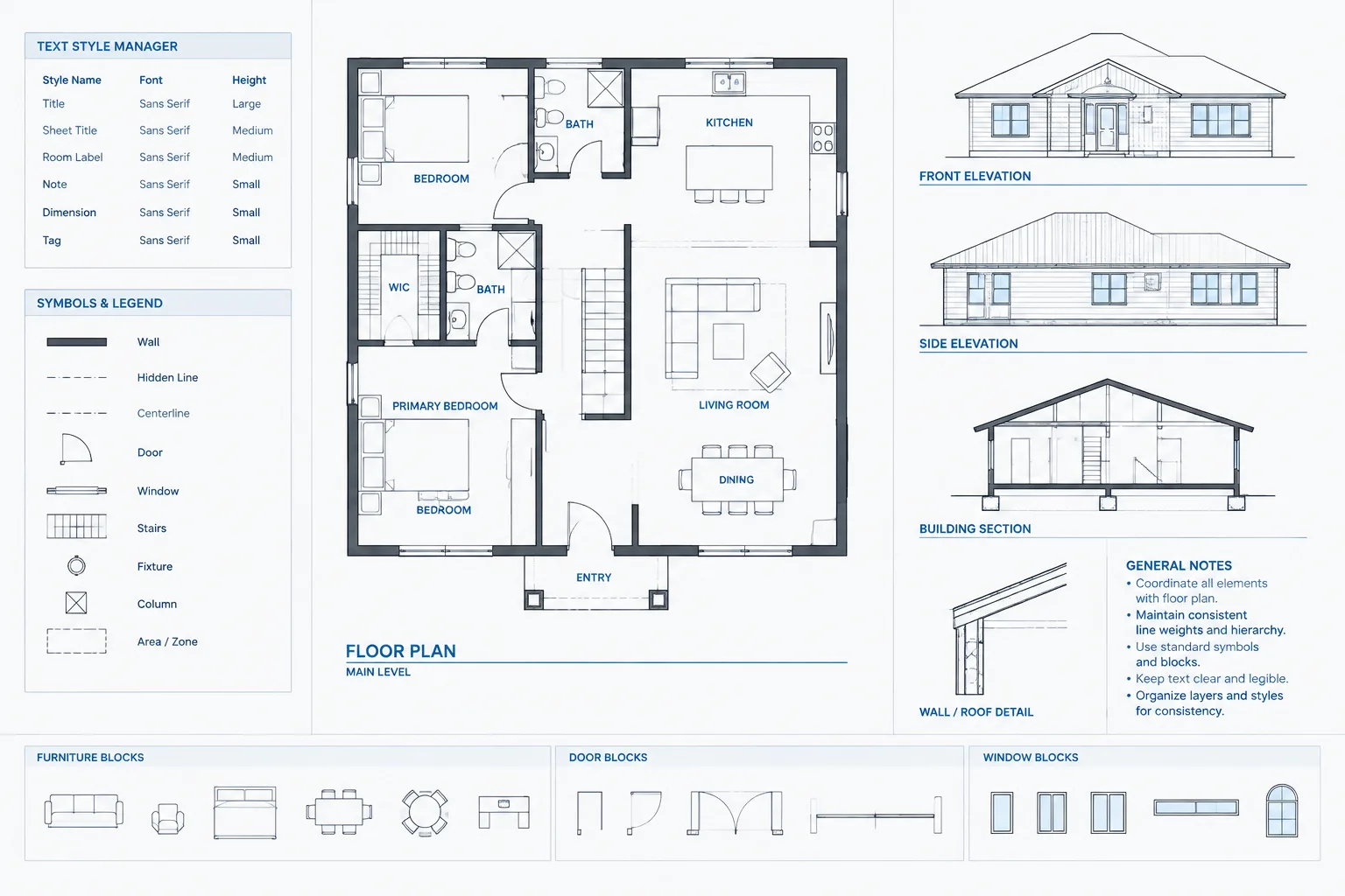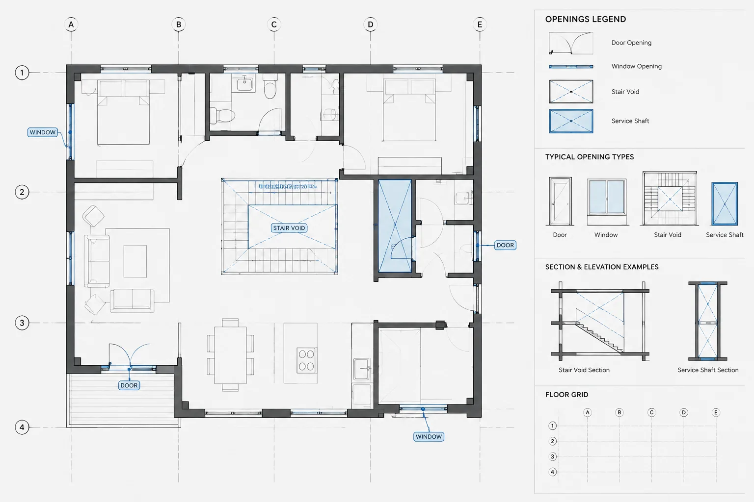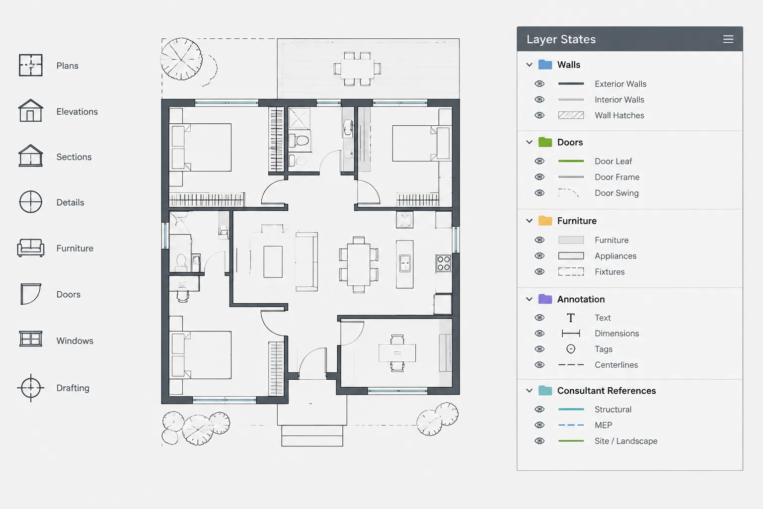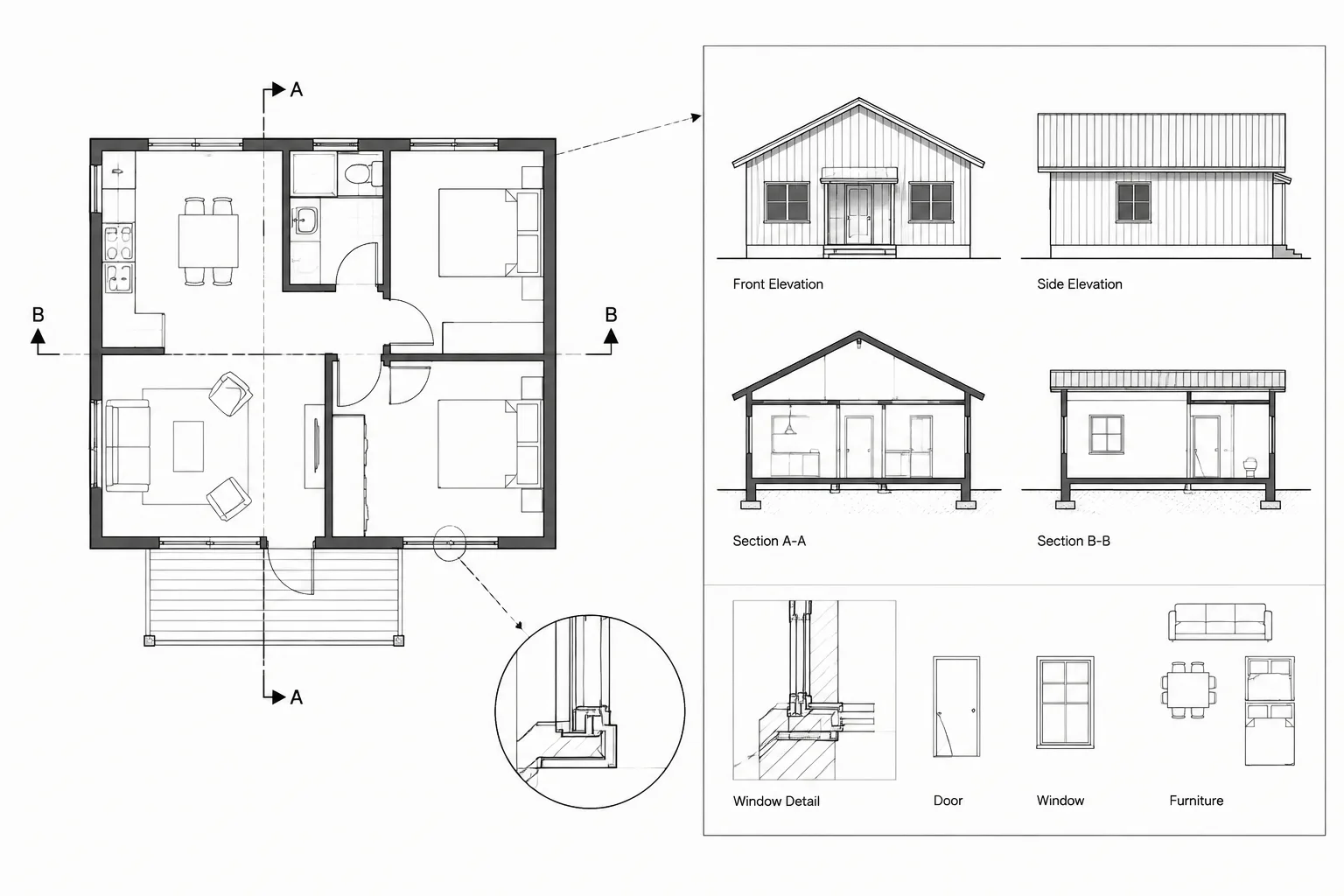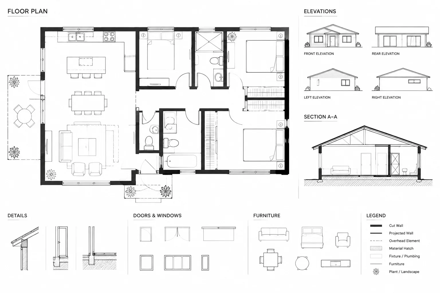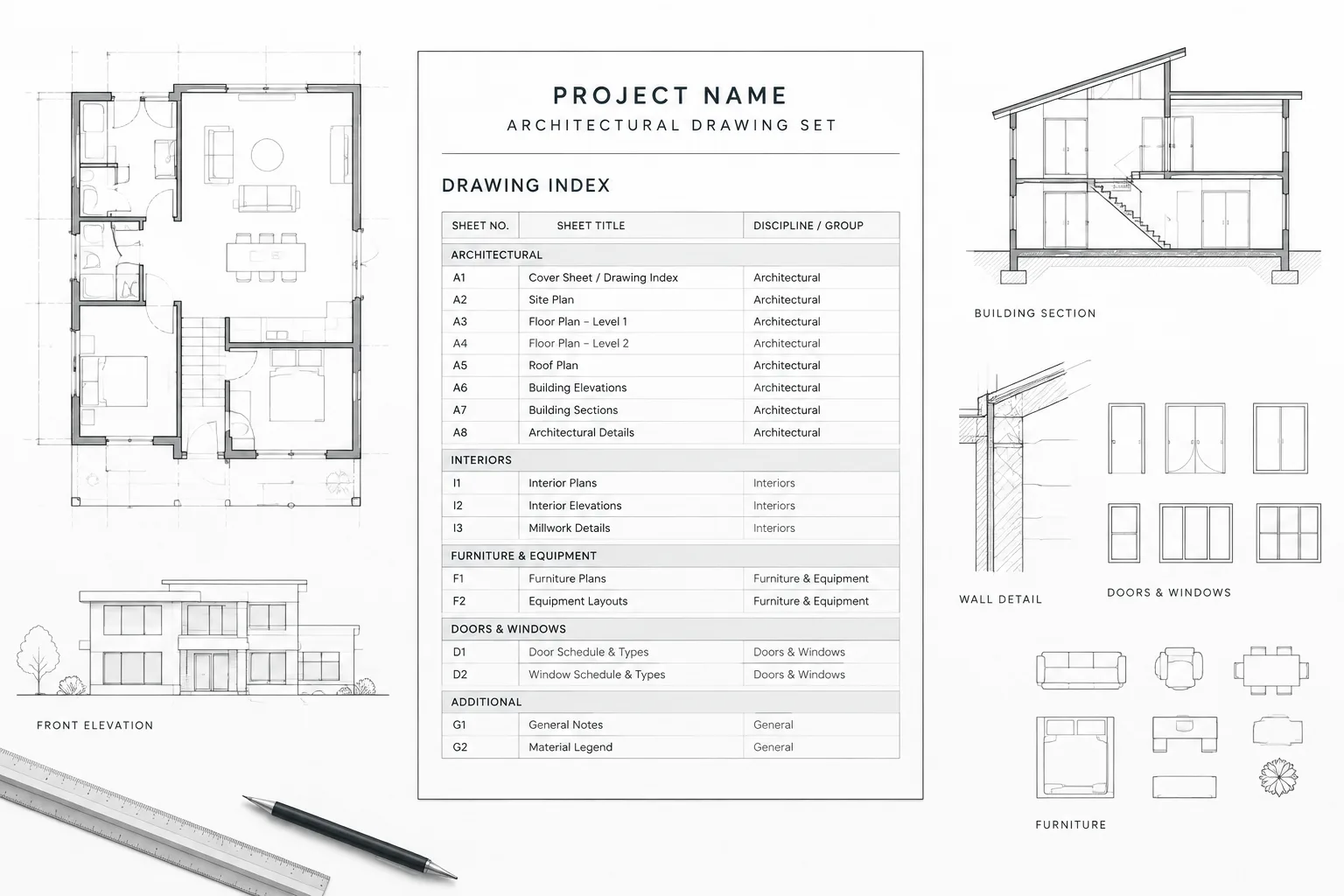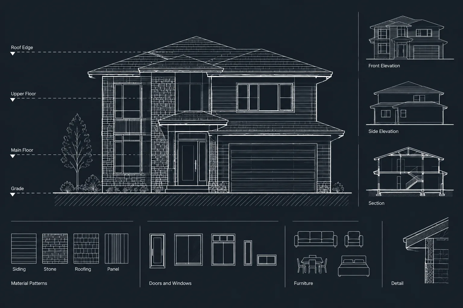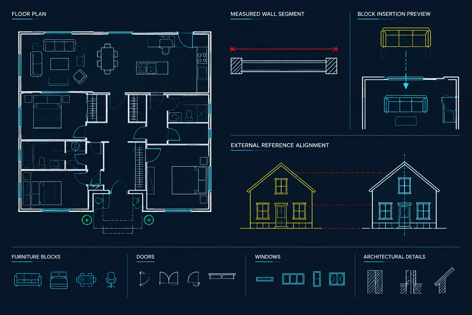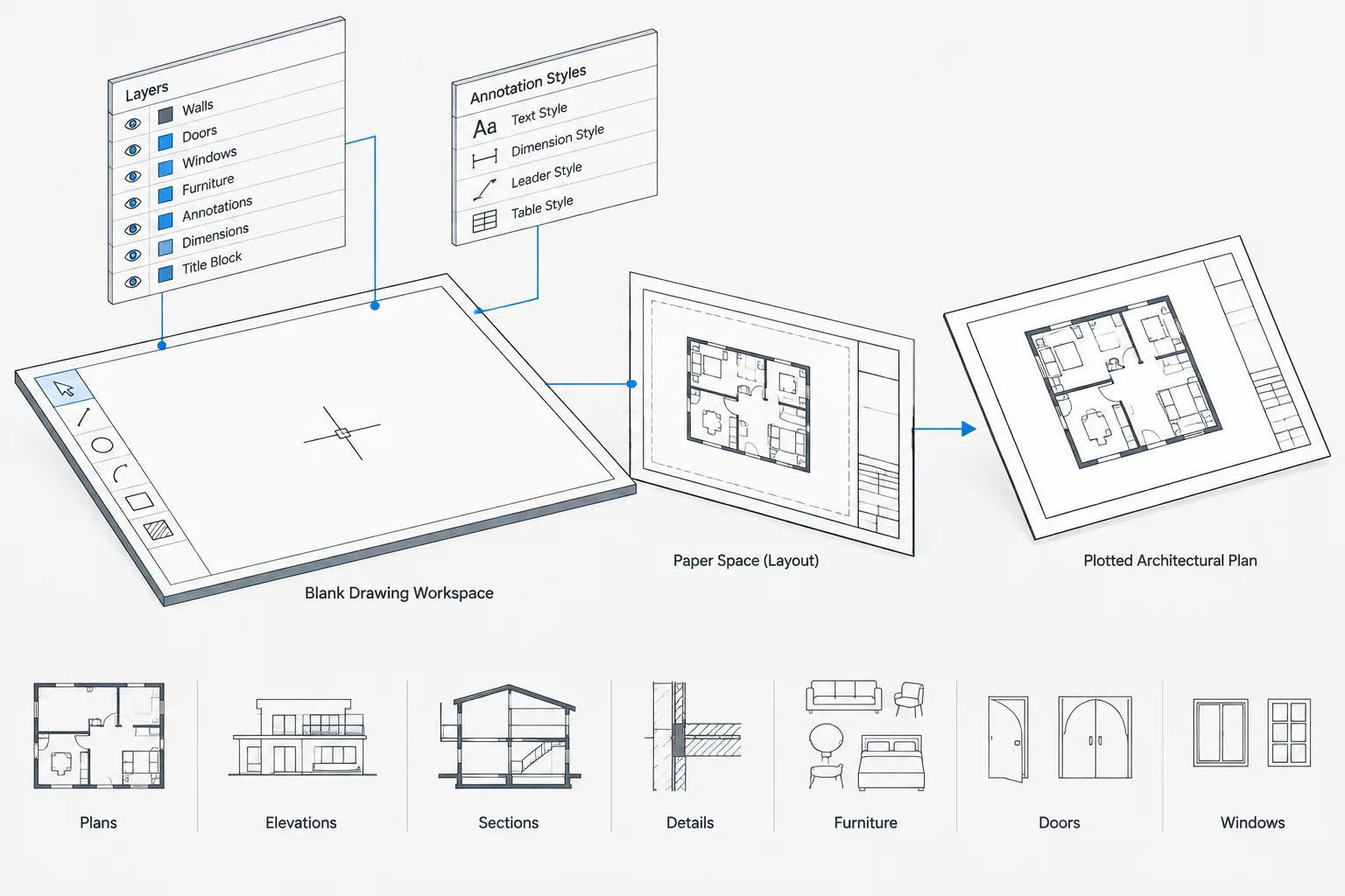
Architectural CAD drawing templates help turn office drafting standards into repeatable starting conditions. Their value comes from more than convenience: a controlled template reduces avoidable variation in layers, annotation, layouts, plotting, and file organization before project work begins.
This guide explains how to plan, test, release, and maintain a template without allowing it to become an overloaded block library or a copy of an old project. Use the workflow as a practical review framework, adapting each decision to the way your team creates, references, checks, and publishes DWG files.
An architectural CAD drawing template gives every new DWG file a controlled starting point. Instead of rebuilding layers, text styles, dimension styles, layouts, and plotting settings for each project, the team begins with a prepared file that reflects its drafting workflow.
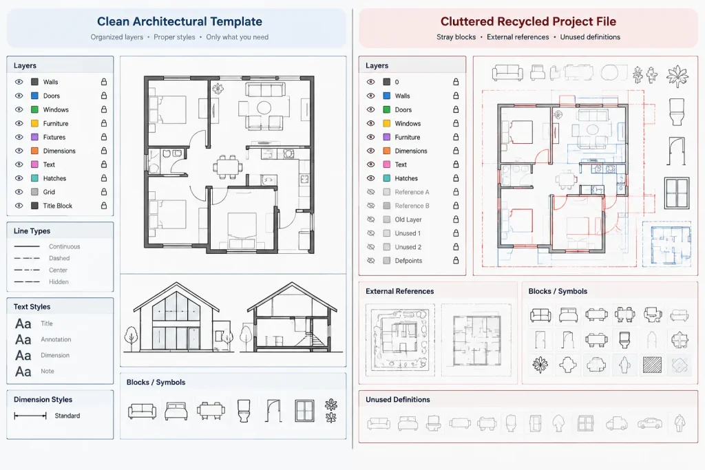
A useful template is not simply an old project drawing with the geometry deleted. It should contain intentional standards, verified settings, and only the resources needed to begin a drawing. The goal is to reduce repetitive setup without carrying project-specific information, unused definitions, or hidden problems into future work.
What an architectural CAD template should accomplish
A template should make correct drafting decisions easier. When a user creates a floor plan, detail, or sheet file, the expected layers and styles should already be available. This improves consistency while reducing manual setup and correction.
A well-managed architectural CAD drawing template can establish:
- Drawing units and related insertion behavior
- Core architectural layers and default properties
- Text, dimension, multileader, and table styles
- Common linetypes and hatch definitions
- Layouts, title block references, and viewport conventions
- Page setups for the office’s usual output methods
- Basic annotation symbols or approved seed content
- File properties, drafting aids, and other controlled settings
The template cannot guarantee that a drawing is coordinated, code compliant, or ready for construction. It provides a technical framework; project-specific design and quality control still require professional review.
Start with a clean source file
Build the template from a clean file rather than copying a completed project. A project DWG may contain imported layers, anonymous blocks, stale references, redundant styles, geolocation data, or objects far from the intended drawing area. Deleting visible geometry does not necessarily remove those definitions.
Before developing the template, confirm the intended drawing units and inspect the file for unnecessary content. Review layers, blocks, linetypes, text styles, dimension styles, layouts, external references, and registered applications. Remove items that do not belong in a general starting file, using appropriate cleanup tools and a controlled review process.
Keep a separate working copy while developing the template. This allows testing and revision without placing an unfinished file into production.
Define the template’s scope
One template does not have to serve every drawing type. A small practice may use one general architectural template, while a larger team may maintain separate starting files for model drawings, detail sheets, presentation plans, or other recurring deliverables.
| Template approach | Useful when | Primary risk |
|---|---|---|
| Single general template | The office uses a compact and consistent CAD system | The file may accumulate settings that many projects never use |
| Model and sheet templates | Model-space geometry and paper-space documentation are stored separately | Shared standards can drift if the files are maintained independently |
| Drawing-type templates | Plans, details, or other drawing families require distinct setups | Too many templates can confuse users and increase maintenance |
Choose the simplest structure that supports the actual workflow. Template names should clearly communicate purpose so users do not have to open several files to find the correct starting point.
Establish units before adding content
Unit decisions affect block insertion, external references, hatch appearance, linetype display, and imported content. Set the template for the measurement system used by the intended projects, then test it with known geometry and a trusted block.
Avoid treating the displayed unit format as proof that the drawing is correctly scaled. A file can show architectural-style measurements while containing geometry created at an unintended size. Verify scale by measuring known objects and by inserting controlled test content.
If the office works in more than one measurement system, separate templates may be safer than repeatedly changing a single template. Blocks and referenced files should also have clearly understood source units.
Build a deliberate core layer list
Include layers that are likely to be used across many architectural drawings, but do not preload every layer ever created by the office. An oversized list makes layer selection slower and encourages users to place objects on layers they do not understand.
For each core layer, review:
- Name and discipline relationship
- Color or other plot-driving property
- Linetype and lineweight
- Plot or non-plot status
- Default visibility behavior
- Whether it should appear in model files, sheet files, or both
Use ByLayer properties as the normal starting point. Object-level overrides may be appropriate in specific situations, but embedding unexplained overrides in template content makes later graphic control more difficult.
Layer descriptions can help users understand purpose, particularly where abbreviated naming is unavoidable. Document any special layers used for viewport boundaries, construction geometry, reference information, or non-plot coordination aids.
Coordinate annotation styles as a system
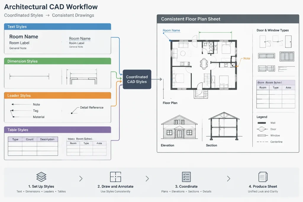
Text, dimensions, leaders, tags, and tables should look related when plotted. Develop these components as a coordinated annotation system rather than as isolated style definitions.
Text styles
Use fonts that are available to everyone who must edit or publish the drawings. Missing font files can cause substitution, altered spacing, and unexpected wrapping. Keep the number of text styles manageable and name them according to function rather than a single project.
Dimension and multileader styles
Check text appearance, arrowheads, extension lines, unit display, spacing, and scale behavior. If annotative styles are used, test them at the scales expected in the office workflow. If the office uses fixed-scale styles instead, make their intended application clear.
Table styles
Coordinate table text with schedules and title block graphics. Confirm that headers, body cells, margins, and borders remain readable after plotting. A generic table style can be useful, but project schedules may still require specialized formatting.
Prepare layouts and page setups carefully
A sheet-oriented template may contain one or more paper-space layouts with title block geometry or a title block reference. Remove placeholder information that could be mistaken for real project data. Fields and attributes should be checked so they do not display stale values from the template’s development file.
Page setups should reflect the office’s available plotting process, including the intended device type, paper configuration, plot style method, orientation, and output area. Because printer names and drivers can vary between computers, test page setups on the production environment rather than assuming they will transfer without adjustment.
If a sample viewport is included, give it a clear purpose. Set its layer appropriately, review its scale behavior, and decide whether it should be locked. Avoid leaving multiple unexplained viewports stacked in the layout.
Be selective with blocks and sample content
Templates can include commonly used symbols, but embedding a large block library makes the starting file heavier and harder to maintain. Frequently revised blocks are usually better managed in a central library or tool palette so they can be updated independently.
Only place example geometry in the template when it teaches or supports the workflow. Useful seed content might include a drawing boundary, a controlled insertion point marker, or a sample annotation object for visual testing. Remove instructional objects from production drawings unless they have a continuing coordination purpose.
Every embedded block should be reviewed for units, insertion point, layer behavior, attributes, nested content, and unnecessary definitions. A block that looks correct in the template can still create problems when inserted, mirrored, scaled, or exported.
Test the template as a real user would
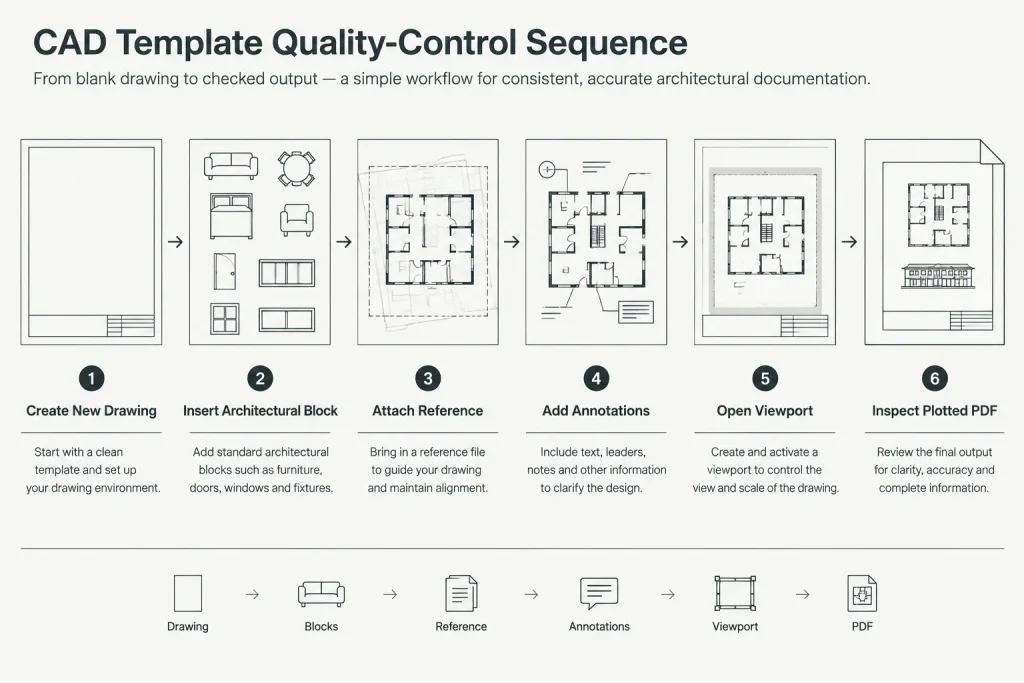
Do not approve a template based only on how it looks when opened. Create a new drawing from it and perform a short production test:
- Draw and measure known geometry.
- Insert a verified architectural block.
- Attach a controlled reference drawing.
- Add text, dimensions, a leader, and a simple table.
- Create or activate a viewport and assign its intended scale.
- Plot or publish a test sheet using the saved page setup.
- Open the resulting PDF and inspect lineweights, text, hatches, clipping, and margins.
- Reopen the DWG and check for warnings, missing resources, or altered paths.
Testing should include another workstation when possible. This can reveal dependencies on local fonts, support paths, plotters, plot style files, or custom content that the template author already has installed.
Control template maintenance
Treat the template as a managed office resource. Store the approved master in a controlled location and limit casual editing. Users can create drawings from the master without modifying the source.
Keep a brief change record that explains what was revised and why. A template update should respond to a clear need, such as correcting a style, improving a layer property, or supporting an established workflow. Avoid frequent cosmetic changes that create inconsistencies between projects.
Existing project files should not automatically be forced to match every new template revision. Determine whether a change is necessary, then import or recreate only the relevant standards using a deliberate process. Replacing settings mid-project can alter plots or annotation unexpectedly.
Common template mistakes
- Using a previous project as the template: This can transfer client information, coordinates, references, and unused definitions.
- Preloading too much content: Excessive blocks, layers, and layouts make the file harder to understand.
- Depending on local resources: Custom fonts or plotting files may not exist on another workstation.
- Leaving default styles unreviewed: Unused or poorly configured styles can be selected accidentally.
- Skipping plotting tests: A template may look correct on screen but produce an unreliable PDF.
- Allowing uncontrolled edits: Multiple unofficial versions undermine the consistency the template was intended to provide.
A reliable template is intentionally modest
The best architectural CAD drawing template is not the one with the most content. It is the one that starts cleanly, supports the office’s real production methods, and behaves predictably when drawings are referenced, annotated, and plotted.
Begin with verified units, a concise layer system, coordinated annotation styles, and tested page setups. Add only resources that offer repeatable value. With controlled maintenance and regular production testing, the template becomes a dependable foundation rather than another source of hidden CAD problems.
How to put the workflow into practice
Template development works best when it is treated as a small standards project rather than an informal cleanup task. Identify the drawing types the template must support, assign responsibility for approval, and separate required resources from optional conveniences. This keeps personal preferences from becoming undocumented office standards.
Review the working environment
Before release, confirm that the template behaves correctly with the fonts, plot resources, support files, reference practices, and shared content available to intended users. A setting that works on the author’s workstation may depend on a local resource that other users cannot access.
Use a controlled approval copy
Keep development files separate from the approved master. Test changes in a disposable drawing created from the candidate template, not only in the template file itself. After approval, place the master where users can start new drawings without casually overwriting the source.
Document decisions, not just settings
A short template guide should explain which starting file to use, what its main layers and styles are intended to control, where shared blocks are stored, and who reviews requested changes. This supporting information makes the template easier to use correctly and easier to maintain when staff or project requirements change.
Template release checklist
- Confirm that the template has a clearly defined purpose and drawing type.
- Verify units with known geometry and controlled insertion content.
- Review layer names, properties, descriptions, and plot behavior.
- Test text, dimension, leader, table, and hatch presentation.
- Inspect layouts, title block data, viewports, and page setups.
- Remove project-specific references, metadata, coordinates, and unused definitions.
- Check shared resources on a production workstation.
- Create a new DWG from the template and complete a plotting test.
- Record approval, ownership, and the reason for later revisions.
A template should be updated when a verified production need justifies the change. Keeping the file concise, documented, and tested is more useful than continually adding content that only some drawings require.
Architectural CAD template FAQ
Is a CAD template the same as a completed project drawing?
No. A template is a controlled starting file containing reusable settings and approved resources. A completed project drawing may carry client data, external references, coordinates, imported definitions, and other information that should not pass into unrelated work.
Should every architectural drawing use the same template?
Not necessarily. A general template may suit a compact workflow, while separate model, sheet, or drawing-type templates may be clearer for teams with distinct production needs. The structure should remain simple enough for users to choose the correct file reliably.
Should a template contain the entire CAD block library?
Usually not. Frequently updated blocks are easier to manage in a controlled shared library. Template content should be limited to resources that provide consistent value at the beginning of most applicable drawings.
Why can a template plot differently on another workstation?
The file may depend on fonts, plot style files, printer configurations, support paths, or other local resources. Testing in the actual production environment helps reveal these dependencies before the template is released.
Should existing projects receive every template update?
No. Changes should be evaluated for their effect on existing annotation, graphics, references, and plotted output. Import only the standards that a project needs, using a reviewed process rather than replacing settings automatically.
Who should be allowed to edit the master template?
The approved master should have clear ownership and controlled editing access. Users can create drawings from it, while proposed revisions are tested and approved before they replace the production version.