Hidden elevation data can make ordinary plan linework difficult to edit even when nothing looks wrong in Top view. The safest response is to diagnose the affected objects, confirm the intended drawing plane, and choose a correction method that does not erase legitimate 3D information.
This guide presents a practical workflow for tracing non-coplanar geometry in architectural DWG files. It also explains why broad, drawing-wide flattening can create new problems and why verification should include both geometric inspection and normal drafting operations.
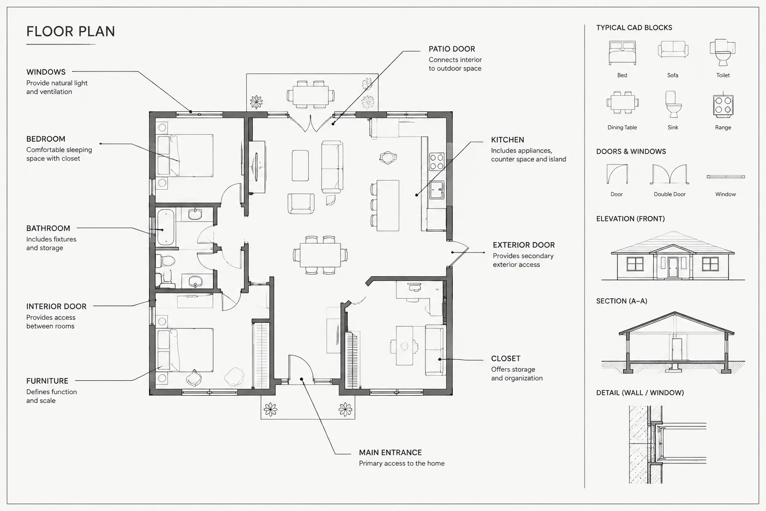
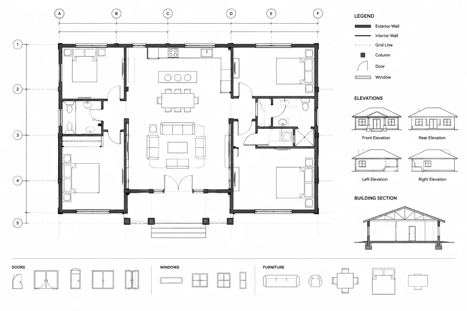
A floor plan may look perfectly flat in Top view while containing lines, polylines, blocks, or text at different Z elevations. This hidden depth often enters a DWG through imported survey data, copied consultant geometry, accidental object snaps, block content, or work performed in a rotated coordinate system.
Stray Z values can interfere with trimming, hatching, measuring, joining polylines, creating boundaries, and calculating areas. They can also make geometry appear displaced when the drawing is viewed from an angle. Correcting the problem requires more than applying a flattening command to the entire file. A controlled workflow should identify which objects are supposed to be two-dimensional, preserve legitimate three-dimensional information, and verify the result.
What non-coplanar geometry means
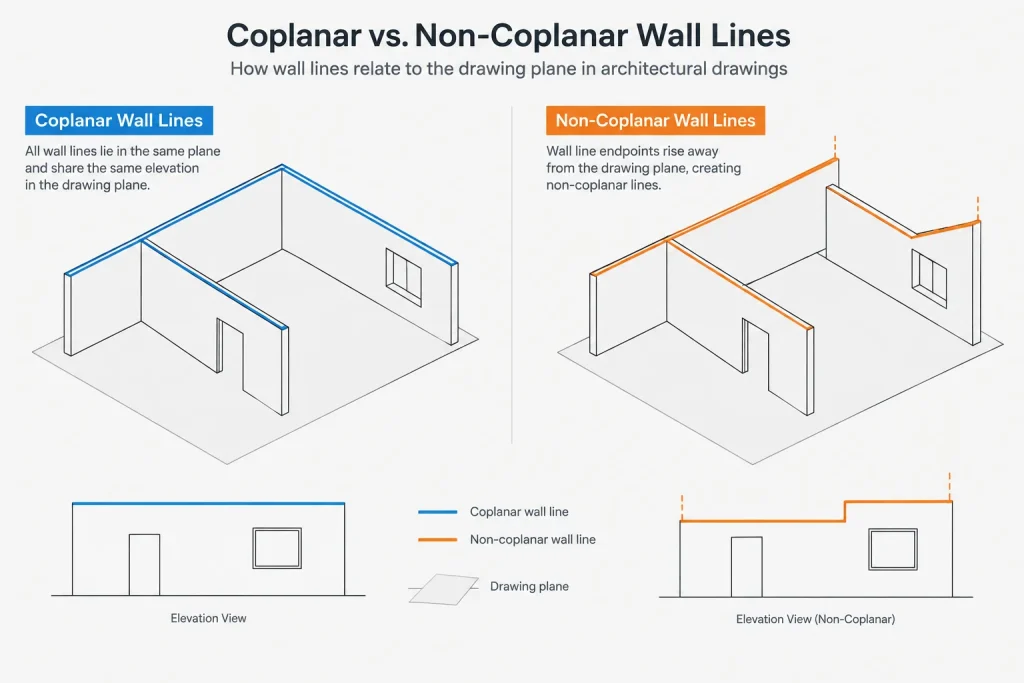
Objects are coplanar when they lie on the same geometric plane. In a conventional 2D architectural plan, most plan linework is expected to share a common working plane. Non-coplanar geometry occurs when some objects have different elevations, endpoints with unequal Z coordinates, or extrusion directions that do not match the intended drawing plane.
The issue is not simply that an object has a nonzero elevation. An entire drawing can be created on a deliberate elevated plane and still be internally consistent. Trouble begins when supposedly related objects do not share the same plane or when their object data conflicts with the project’s drafting method.
Not every elevated object is an error. Three-dimensional site information, massing models, solids, topographic data, and discipline models may intentionally use Z coordinates. Before changing anything, determine whether the file is meant to be a flat drafting background, a hybrid drawing, or a true 3D model.
Common symptoms in architectural drawings
Non-coplanar objects are not always visible in a normal plan view. They usually reveal themselves through editing problems or unexpected display behavior.
- Lines that appear to meet cannot be joined into one polyline.
- Trim or Extend does not produce the expected result.
- A hatch cannot find a boundary that looks closed.
- Area calculations fail or return results from the wrong boundary.
- Fillet does not connect two apparently intersecting objects.
- Dimensions or measurements report unexpected distances.
- Blocks appear to float above or below adjacent plan geometry in an isometric view.
- Copied objects land on an unintended elevation.
- Polylines contain vertices with inconsistent elevation data.
- Objects disappear or seem offset after a coordinate-system or view change.
These symptoms can also have other causes, including tiny gaps, duplicate objects, incorrect object snaps, proxy objects, and damaged geometry. Elevation should therefore be investigated rather than assumed.
How stray Z values enter a DWG
Copied consultant or survey information
Civil and survey drawings often use meaningful three-dimensional coordinates. Copying their geometry directly into an architectural plan can introduce elevated polylines, points, blocks, or contours. The source information may be correct in its original context but inappropriate for a flat plan background.
Object snapping to elevated geometry
A drafter may snap to a point within a 3D object, an elevated reference, or a block containing hidden depth. New lines can then inherit endpoints at different elevations even though they appear normal from above.
Blocks with internal elevation errors
A block reference can report a sensible insertion elevation while objects inside its definition contain stray Z coordinates. Correcting only the reference may not solve the internal problem. Nested blocks can make this condition harder to detect.
Changes to the working coordinate system
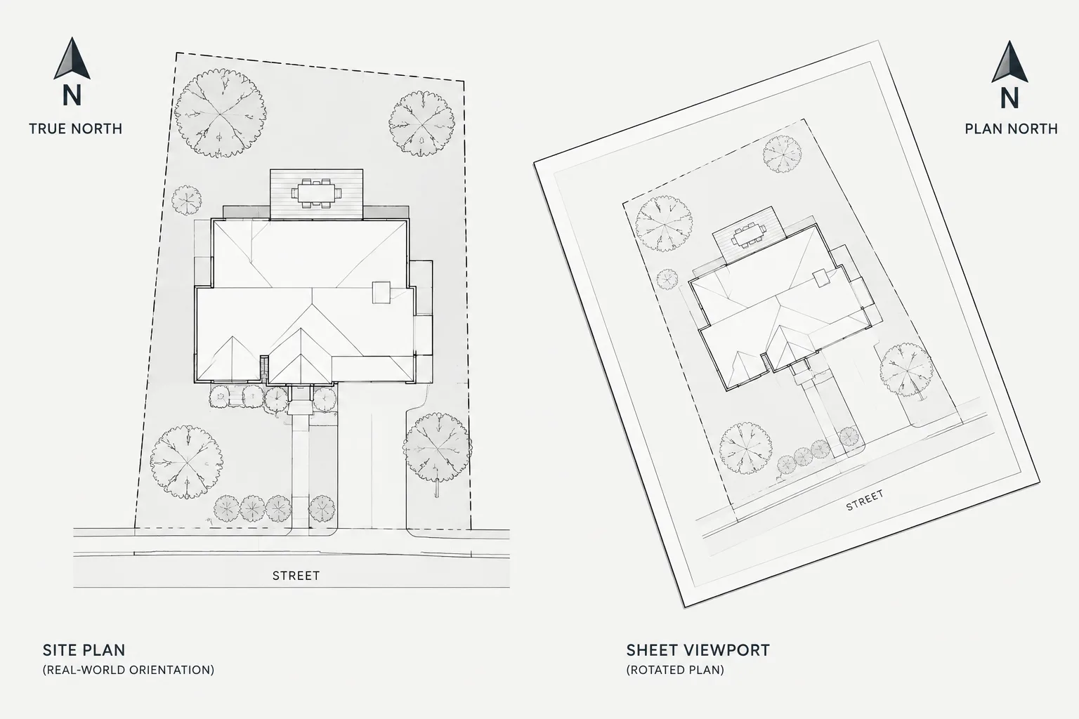
Drafting in a rotated or object-aligned coordinate system can produce geometry that is flat relative to that system but not aligned with the expected world plane. A plan can therefore look correct in one view and appear tilted in another.
Imported or converted files
Geometry originating in PDFs, modeling applications, mapping files, or other CAD platforms may contain unusual elevations, normals, or object types. Conversion can also split simple-looking elements into many small segments with inconsistent data.
A controlled diagnosis workflow
1. Protect the source file
Save a separate cleanup copy before editing. If the drawing is an external reference, decide whether the source should be corrected by its owner or whether a project-specific cleaned background is appropriate. Avoid silently changing shared consultant data.
2. Confirm the intended coordinate context
Identify the active user coordinate system and return to the project’s expected working system before diagnosing elevations. Restore a plan view aligned with that system. This separates genuine Z-coordinate problems from display conditions caused by a tilted view.
3. Inspect the drawing from the side
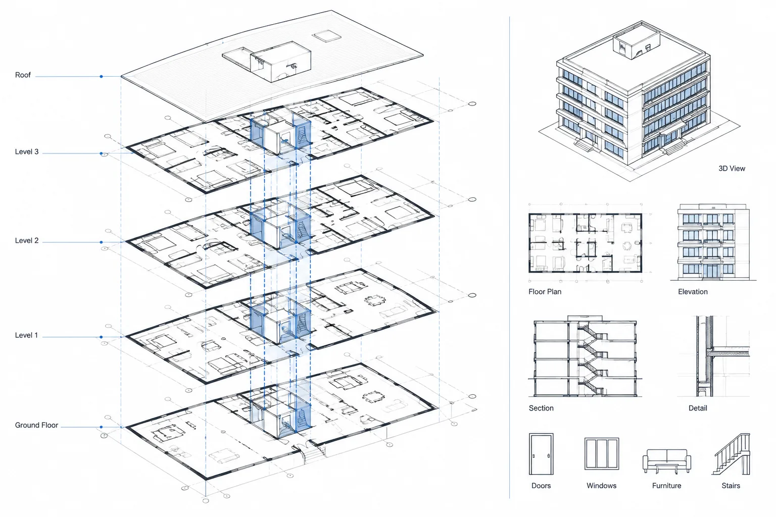
Switch temporarily to a side or isometric view and zoom to the drawing extents. Flat plan geometry should read as a thin plane. Objects above or below it may appear as separate bands, diagonal segments, or isolated clusters.
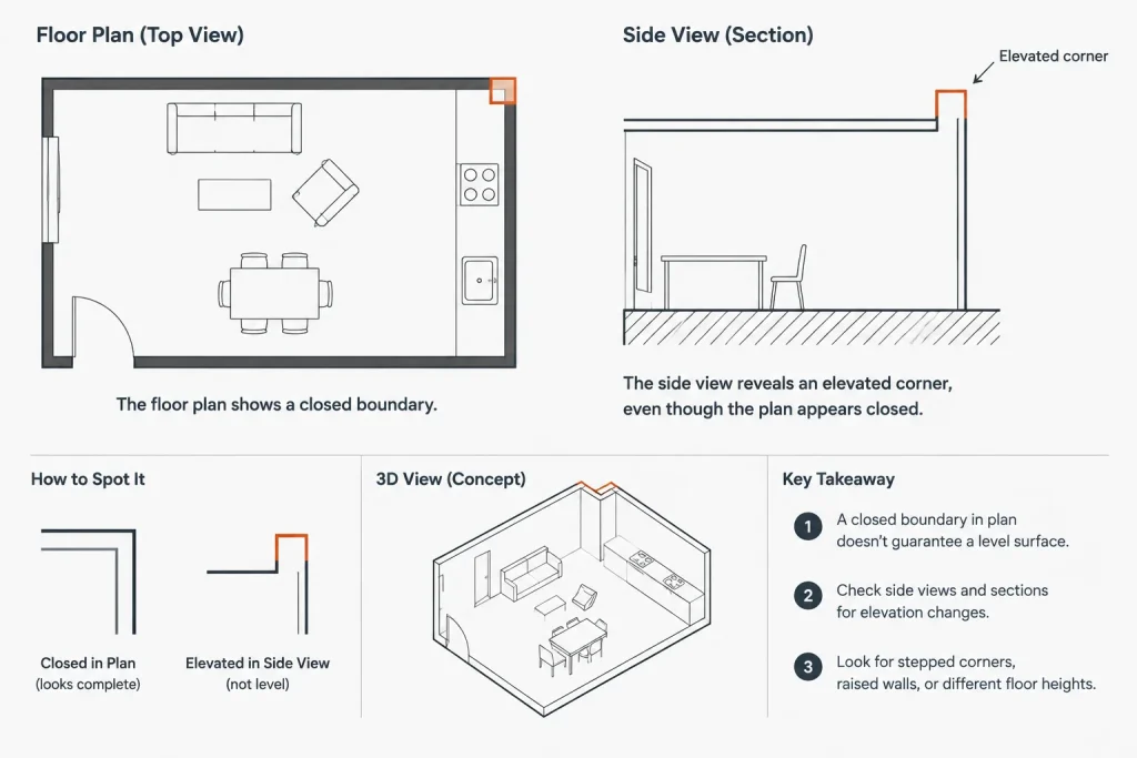
Large coordinate extents can make small elevation differences difficult to see. Select a limited suspect area and inspect it closely rather than relying only on the entire drawing extents.
4. Check object properties
Select suspect objects individually and review the properties relevant to their type. A line may have different start and end Z coordinates. A lightweight polyline may have an elevation value. Text, blocks, hatches, and other objects can each store placement information differently.
The List command can provide additional geometric information when the Properties palette does not make the problem obvious. Compare a faulty object with a nearby object known to be correct.
5. Isolate by object type or source
Do not select the entire drawing immediately. Work through logical groups such as wall linework, consultant backgrounds, imported contours, annotation, and blocks. Layer isolation and filtered selection can help identify where the bad geometry originated.
| Object condition | Useful check | Likely response |
|---|---|---|
| Whole object is elevated uniformly | Review its elevation or insertion position | Move or reset it to the intended plane |
| Line endpoints have different Z values | Compare start and end coordinates | Correct the endpoints or redraw the line |
| Polyline will not join neighboring geometry | Inspect elevation, vertices, and object type | Normalize or reconstruct the boundary |
| Block looks flat but behaves incorrectly | Open and inspect the block definition | Correct internal objects and verify references |
| Survey or site data contains meaningful heights | Confirm its coordination purpose | Preserve the source and create a separate 2D background if needed |
Methods for correcting non-coplanar objects
Edit object elevations directly
For a small, clearly identified selection, changing elevation-related properties is often the safest method. This keeps the correction limited and makes the result easy to review. The available properties vary by object type, so do not assume one field controls every object.
Move uniformly elevated objects
If an object is flat but located above or below the intended plane, it can be moved along the relevant axis by a verified displacement. This method is unsuitable for a line or polyline whose individual vertices have inconsistent Z values.
Use flattening tools selectively
AutoCAD includes a Flatten command that projects selected geometry onto the current viewing plane. It can be useful for converting a controlled copy of 3D or elevated linework into a 2D drafting background. Because the result depends on the active view and the selected object types, establish the correct view first and test the command on a small sample.
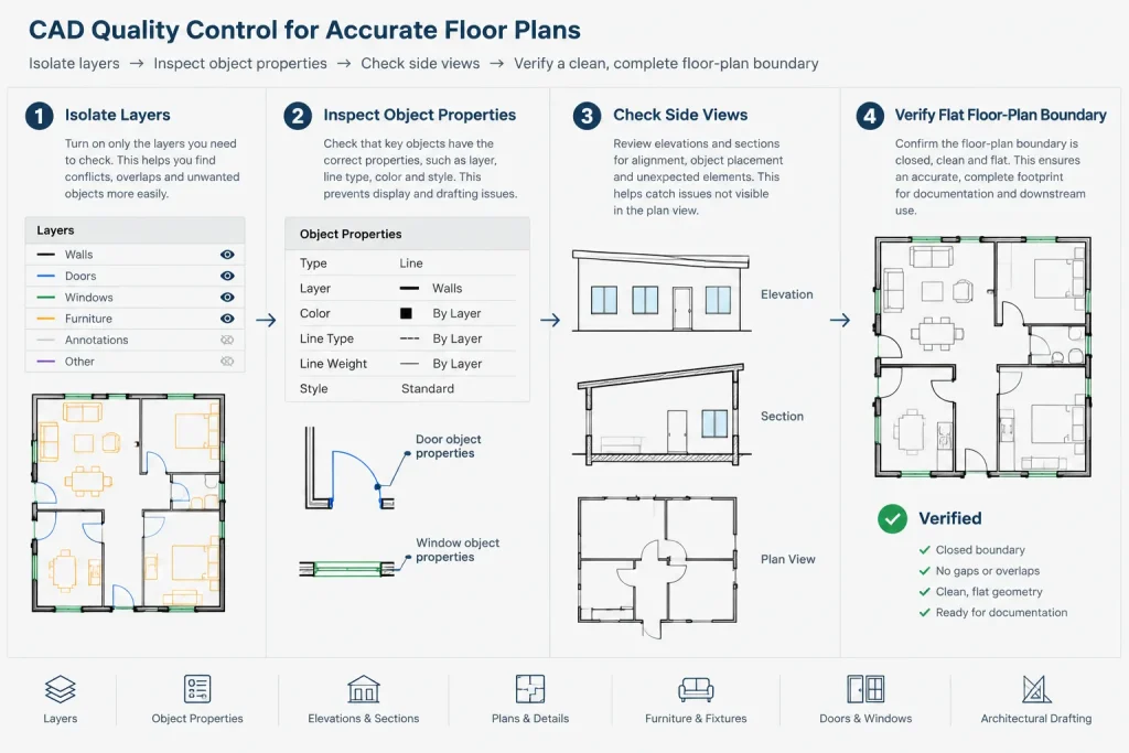
Flattening should not be treated as a universal repair button. It may alter object representation, reduce useful depth information, or create results that require cleanup. Never apply it indiscriminately to survey surfaces, solids, coordinated 3D elements, or data that must retain real elevations.
Repair block definitions at the source
When several instances of the same block have identical problems, inspect the definition rather than correcting each reference. Check nested content as well as visible linework. After editing, verify that insertion points, attributes, and intended orientation remain correct.
Redraw simple damaged geometry
For short boundaries or isolated linework, redrawing may be more reliable than repairing converted or malformed objects. This is especially true when a polyline contains numerous tiny segments, mixed elevations, or geometry that cannot be edited predictably.
Verification after cleanup
A drawing is not verified merely because it looks flat again. Test the operations that originally exposed the problem.
- Inspect the corrected area from a side or isometric view.
- Confirm that intended plan objects share the project’s working plane.
- Join boundary segments where continuous polylines are required.
- Create a temporary hatch inside a representative enclosed area.
- Recheck area and distance measurements against known geometry.
- Test Trim, Extend, and Fillet on representative intersections.
- Regenerate the drawing and review relevant paper-space viewports.
- Check edited blocks in more than one location.
- Confirm that legitimate site or model elevations were not removed.
Preventing future elevation contamination
Prevention starts with understanding incoming files. Review consultant and imported drawings before copying their contents into production plans. When three-dimensional source data is needed only as a graphic background, create and label a controlled 2D derivative rather than modifying the authoritative source.
Keep project coordinate practices documented, and verify the active coordinate system before drafting after working in a rotated view. Use object snaps carefully around 3D references. New blocks should be reviewed from both plan and side views before being added to a shared library.
Finally, include a planarity check in DWG quality control. A quick side-view inspection and a few object-property checks can catch hidden elevation errors before they spread into hatches, room boundaries, details, and issued sheets. The goal is not to force every project file into two dimensions, but to keep each drawing consistent with its intended purpose.
Choosing the least disruptive repair
The best correction is usually the smallest one that restores the intended relationship between objects. Begin with the suspect area rather than the entire file, and separate drafting linework from survey, site, modeling, and consultant data before changing elevations.
- Use property edits when a limited group of objects has clearly incorrect placement data.
- Correct the source definition when the same problem appears repeatedly in instances of one block.
- Reconstruct a boundary when converted or fragmented geometry is less reliable to repair than to redraw.
- Create a controlled 2D derivative when elevated source information must remain authoritative but a flat background is needed for architectural drafting.
- Use projection or flattening tools cautiously only after confirming the working coordinate system, view, selection, and intended result.
Documenting the cleanup
Geometry cleanup can affect coordination, especially when the file originated outside the architectural team. Record which layers, blocks, references, or imported objects were changed and whether the corrected file is authoritative or merely a project-specific background.
If legitimate 3D information was preserved separately, make that distinction clear in the file name, drawing notes, or project documentation. This helps prevent a flattened derivative from being mistaken for coordinated elevation data later in the workflow.
A practical acceptance check
Review the repaired area in more than one view, then repeat the operation that first revealed the fault. Successful trimming alone does not prove that every related boundary is planar, just as a successful hatch does not confirm that all consultant geometry retained its intended elevation.
A reliable acceptance check combines visual inspection, object-property review, editing tests, boundary tests, and confirmation that unaffected 3D content remains intact. This turns planarity cleanup into a controlled quality-assurance task rather than a cosmetic fix.
Frequently asked questions
Why do lines look connected but refuse to join?
Their endpoints may align in plan while having different Z coordinates. Other possible causes include small gaps, overlapping segments, incompatible object types, or damaged geometry, so elevation data should be checked alongside basic boundary cleanup.
Should every object in an architectural DWG have the same elevation?
No. Conventional plan linework may be intended to share one working plane, while topography, site data, solids, massing, and coordinated model elements can contain meaningful depth. The drawing’s purpose determines what should remain elevated.
Why can a block remain non-coplanar after its insertion elevation is corrected?
The block definition may contain elevated linework, nested blocks, attributes, or objects with inconsistent internal coordinates. Correcting the reference position does not automatically repair geometry stored inside the definition.
Is Flatten always the fastest solution?
It may be quick for a controlled selection, but it is not automatically the safest solution. The result depends on the active view, selected objects, and source geometry. Test it on a copy and verify the resulting object types and drafting behavior.
Can a rotated coordinate system make flat geometry appear incorrect?
Yes. Geometry may be planar relative to one coordinate system while not matching the project’s expected working plane. Confirm the active coordinate system and view before deciding that object elevations are wrong.
How can non-coplanar geometry be detected before issuing drawings?
Add planarity checks to CAD quality control. Inspect relevant linework from a side or isometric view, review properties for representative objects, and test common operations such as joining boundaries, hatching, measuring, trimming, and calculating areas.