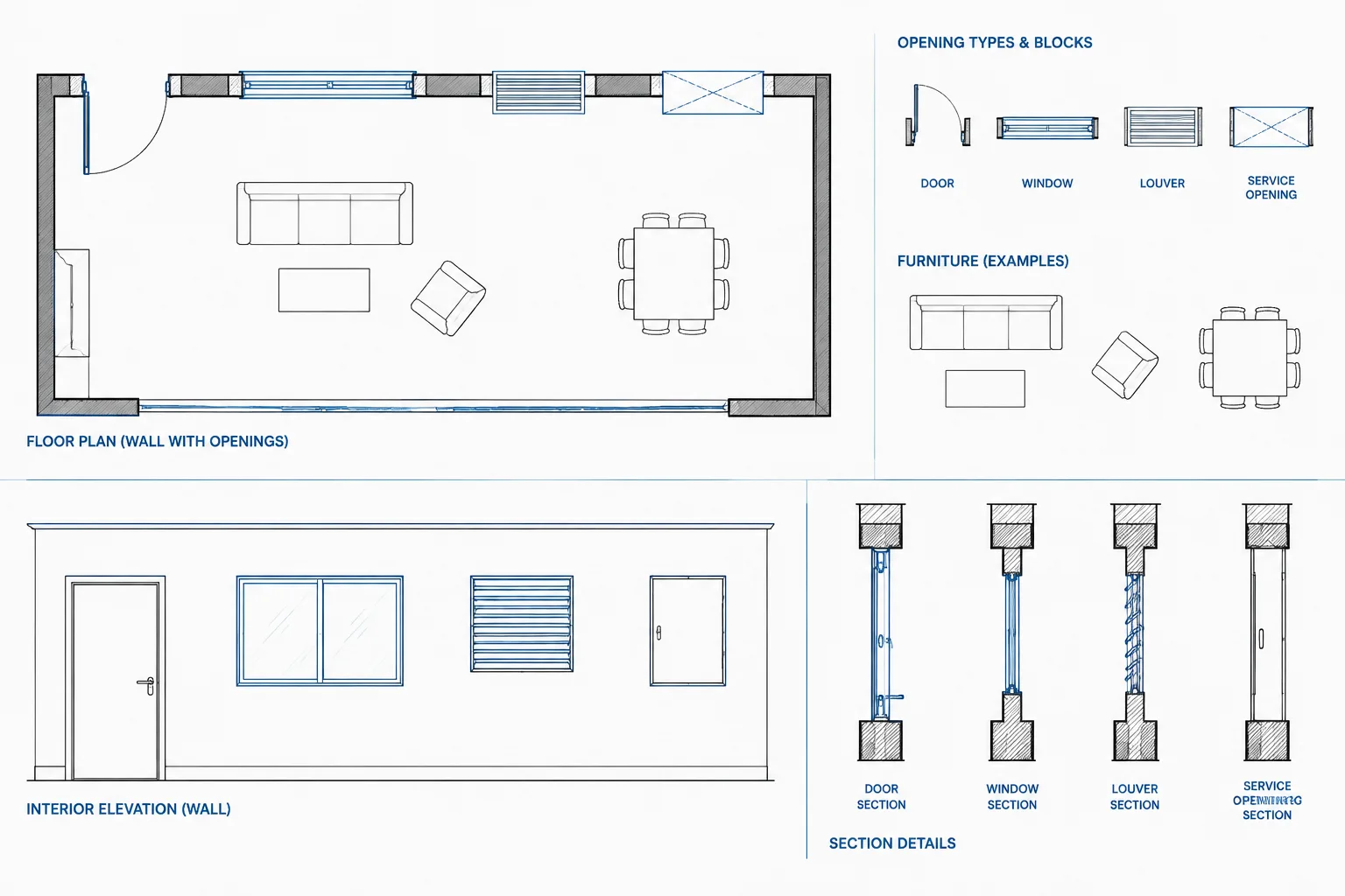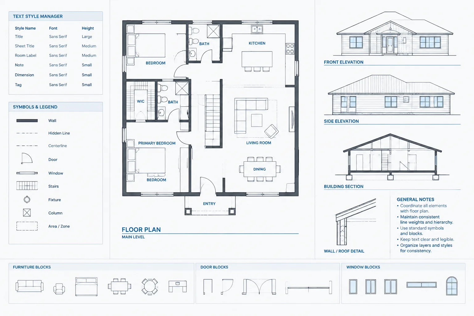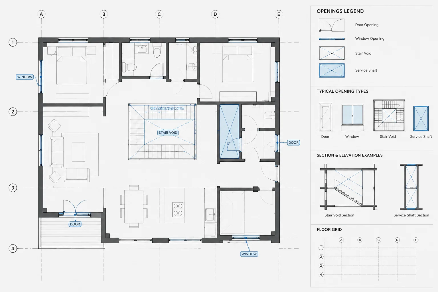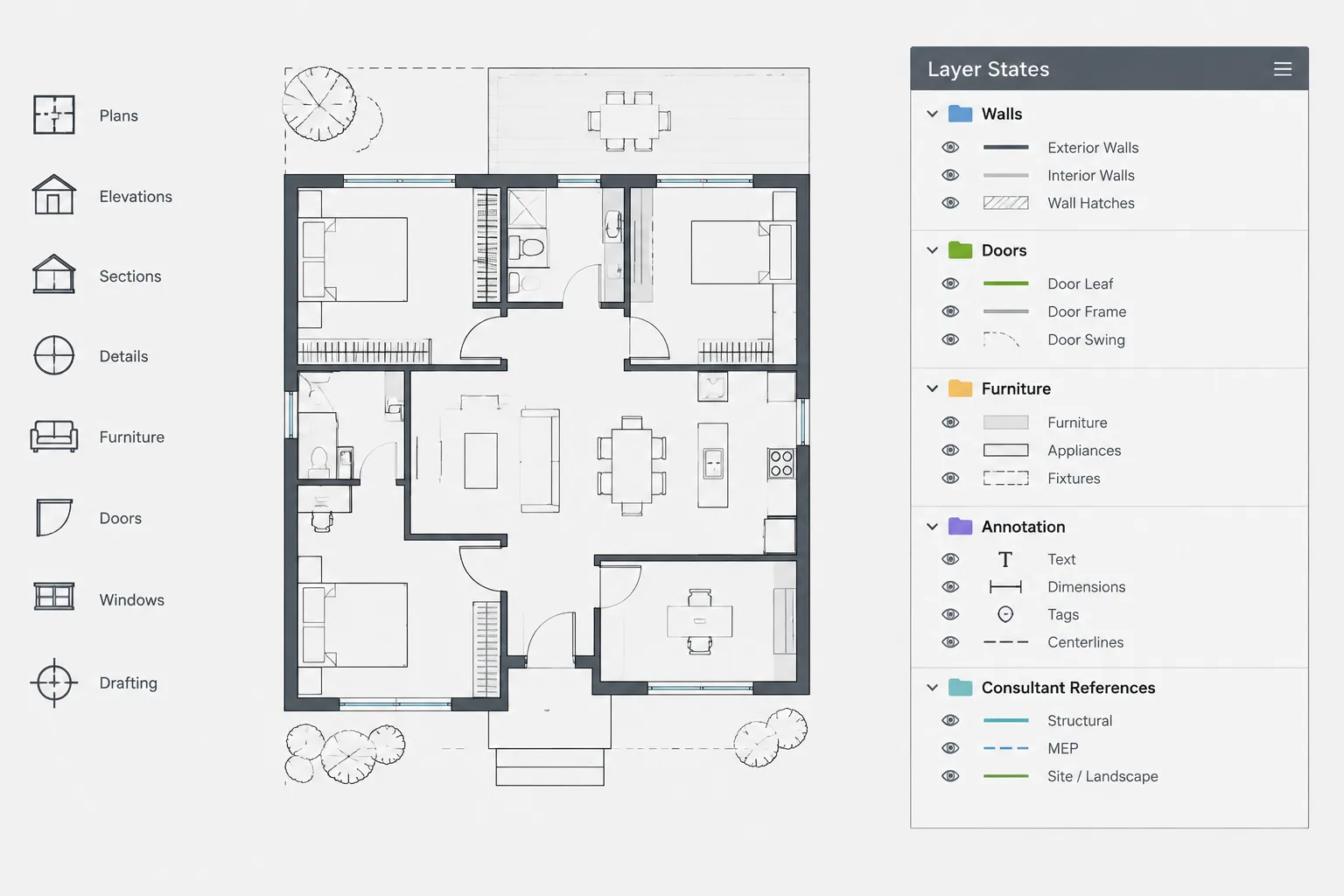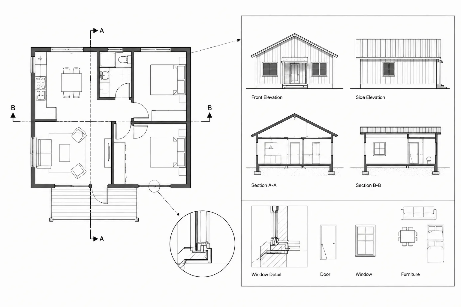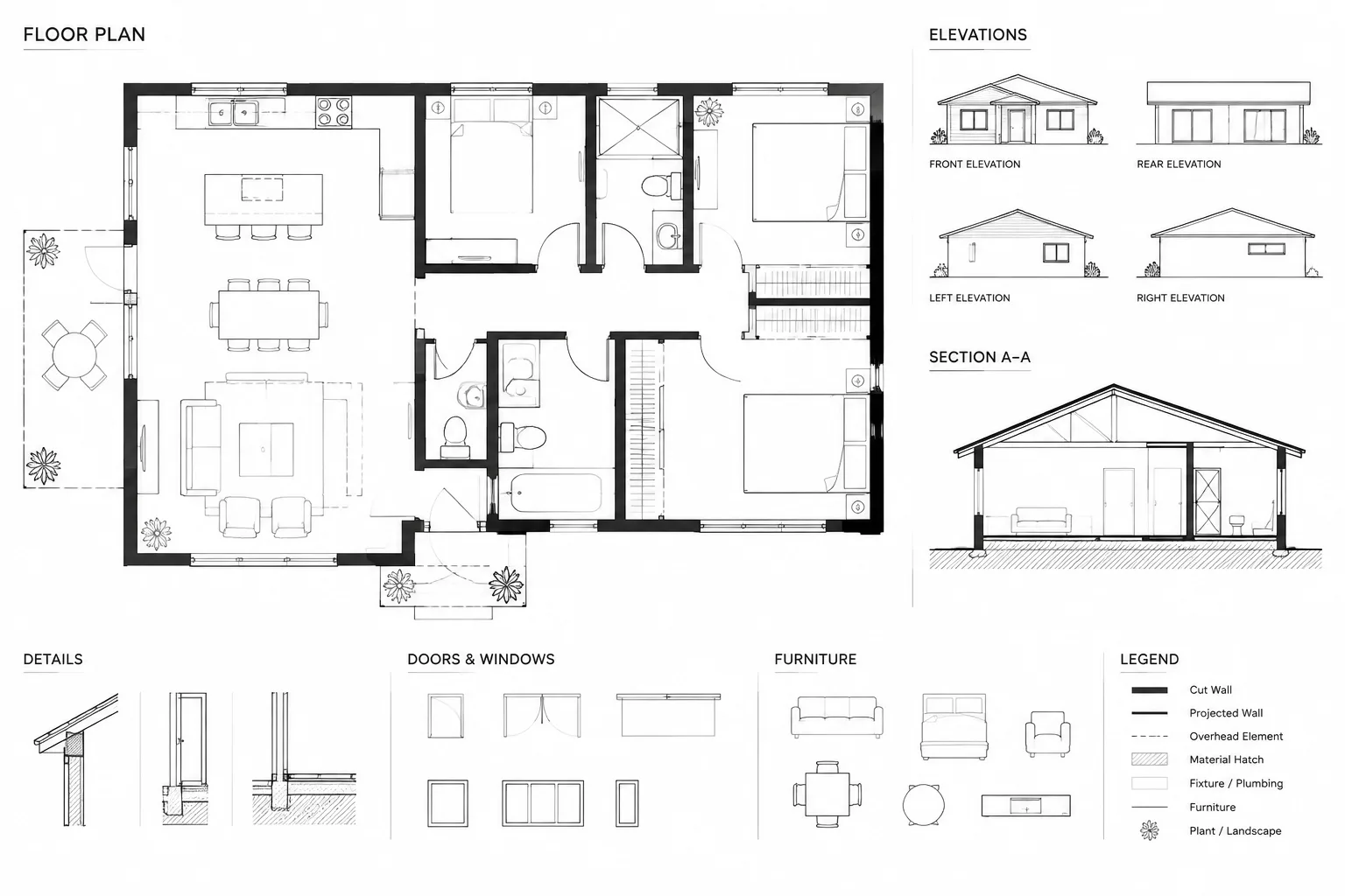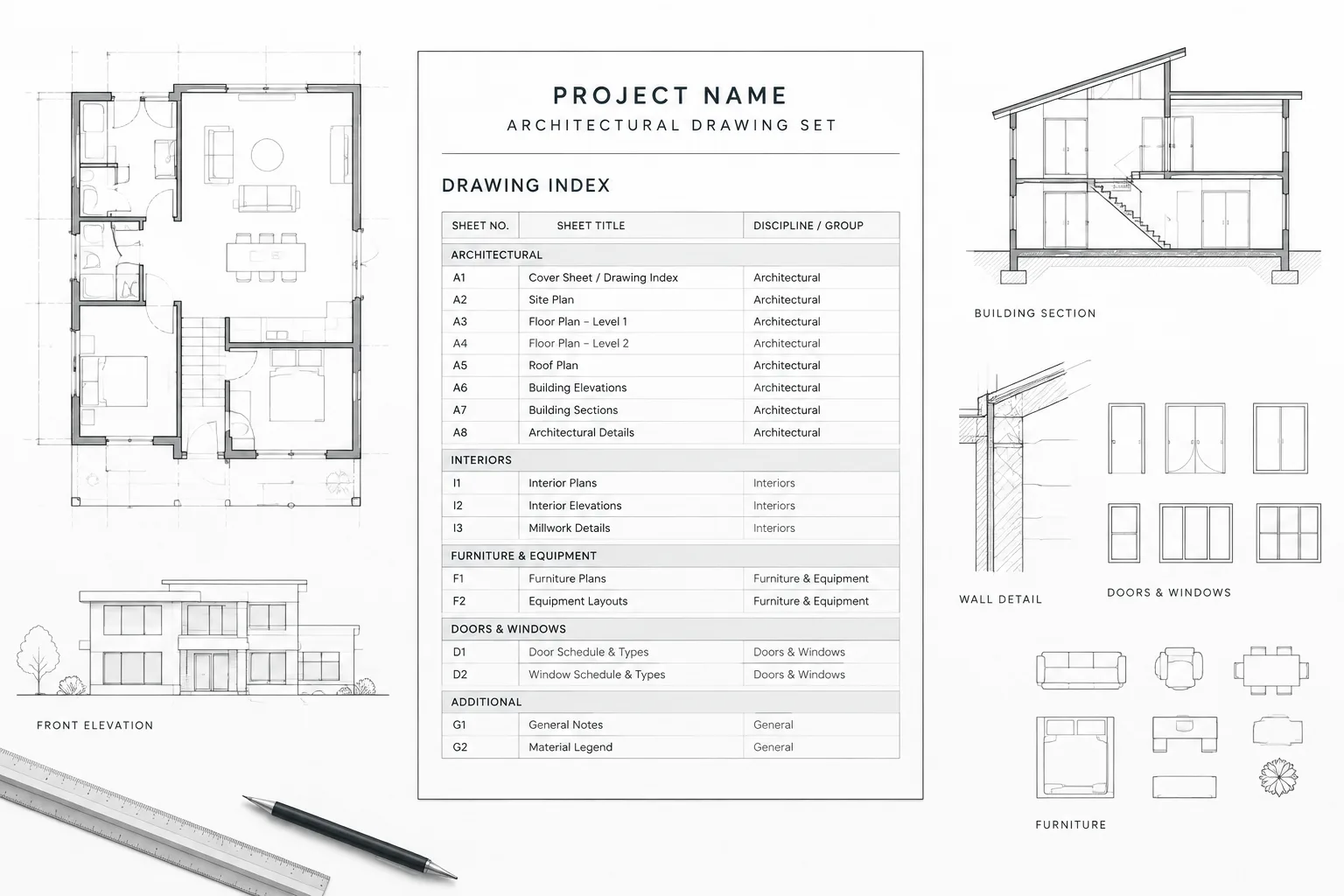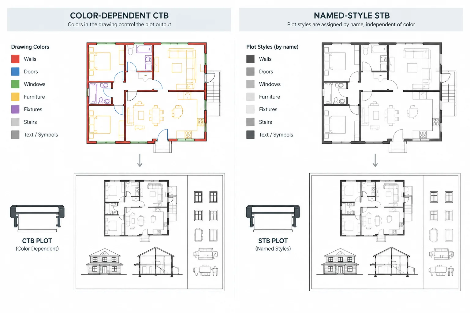
CTB vs. STB plot styles is less a question of which file type is superior and more a question of how plotting intent is communicated. A dependable architectural CAD workflow connects object properties, layers, external references, page setups, and plot-style files so that drawings retain a clear graphic hierarchy when published.
This guide explains how each system works, where coordination problems commonly occur, and what to review before adopting, converting, or troubleshooting a project plotting standard. The goal is predictable output across sheets and users rather than a last-minute attempt to correct graphics during publishing.
Plot styles control how CAD geometry is translated from a drawing into printed sheets and PDFs. In architectural work, they often influence lineweight, plotted color, grayscale treatment, screening, and other output properties. A poorly coordinated plot-style setup can make an otherwise accurate drawing difficult to read.
The two primary AutoCAD plot-style systems are color-dependent plot styles, stored in CTB files, and named plot styles, stored in STB files. Both can produce clear architectural documents. The important issue is not which system is universally better, but whether the drawing, layer standards, page setups, external references, and office procedures all follow the same system.
What Is a CTB Plot Style?
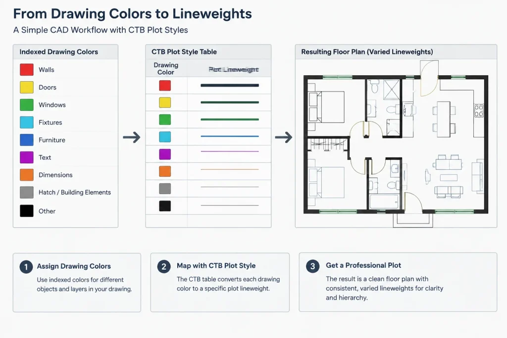
A CTB workflow uses indexed object colors as the main connection between drawing geometry and plotted appearance. A specific drawing color can be mapped to a particular output treatment, such as a heavier line, a lighter line, grayscale, or screened output.
For example, an office might assign different indexed colors to cut walls, doors, fixtures, annotation, overhead elements, and background information. The CTB file then translates those colors into the desired printed hierarchy.
This approach makes color part of the drafting system. Changing an object’s color may change how it prints, even when the layer name and geometry remain unchanged. That relationship is powerful, but it also means users must understand the office color conventions.
Common strengths of a CTB workflow
- Drafting colors provide an immediate visual clue about expected plotted weight.
- A consistent office color chart can be applied across many drawing types.
- Layer colors can efficiently control large groups of objects.
- The system is familiar to many architectural production teams and consultants.
Common CTB coordination risks
- Changing a color for screen visibility can unintentionally change printed output.
- Imported blocks may use colors that do not match the project mapping.
- Object-level color overrides can bypass the intended layer hierarchy.
- Users may incorrectly assume that two similar-looking screen colors will print alike.
What Is an STB Plot Style?
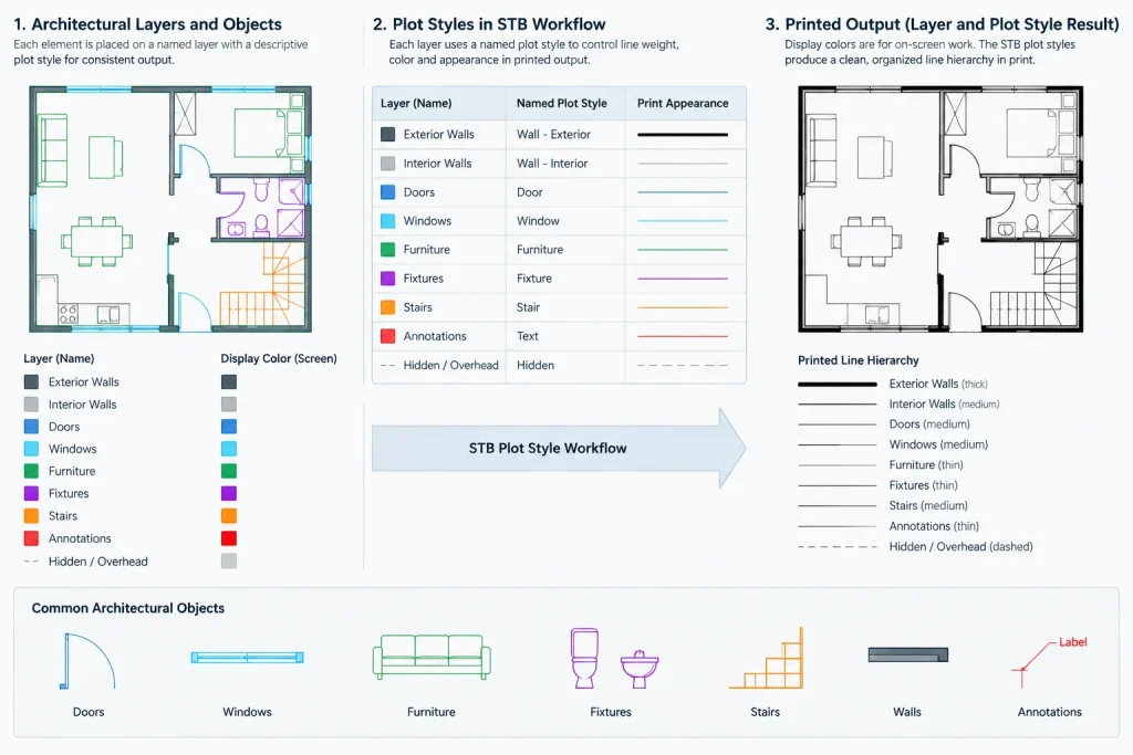
An STB workflow uses named plot styles rather than relying on indexed color as the primary output key. A layer or object can be assigned a descriptive plotting treatment while its display color is managed separately.
Named styles can represent graphic roles such as heavy, medium, light, screened, or full-color output. The actual names should reflect the office’s drafting logic rather than a particular project. A clear naming system helps users understand why a plotting treatment is assigned.
Because display color and plot style can be separated, an STB drawing can use color for discipline recognition, editing clarity, or visual organization without automatically tying every color change to a different lineweight.
Common strengths of an STB workflow
- Plotting intent can be expressed with descriptive style names.
- Display colors can be adjusted without necessarily changing lineweight.
- The plotting system can align closely with graphic roles and document hierarchy.
- Users do not have to memorize a color-to-lineweight chart when styles are clearly named.
Common STB coordination risks
- Objects may carry unexpected style assignments after copying between files.
- A vague or oversized list of named styles can become difficult to manage.
- Users accustomed to CTB files may incorrectly expect color alone to determine output.
- External references and legacy content require careful output testing.
CTB vs. STB at a Glance
| Coordination issue | CTB approach | STB approach |
|---|---|---|
| Primary plotting key | Indexed object color | Named plot style |
| Meaning of display color | Often directly related to printed appearance | Can be managed separately from plotting treatment |
| Typical user decision | Select the correct layer or color | Select the correct layer or named style |
| Office documentation | Color-to-output mapping | Style-name definitions and assignments |
| Main coordination concern | Accidental color overrides | Incorrect or missing named-style assignments |
A drawing is configured to use one of these plot-style systems. CTB and STB files are not interchangeable simply by changing a file extension or selecting a different table. If a project must be converted, perform the conversion on controlled copies and review every sheet afterward.
How to Choose a System for an Architectural Project
Start with the requirements of the organization responsible for issuing the drawings. If an established office template, consultant package, or client standard already uses one system, introducing the other system may create more risk than benefit.
For a new internal standard, consider how the team thinks about graphics. A CTB system may suit an office that uses disciplined color-based drafting. An STB system may suit a team that wants explicit plot-style names and greater separation between screen color and printed weight.
Also consider the source of project content. Reusing legacy details, consultant backgrounds, and block libraries is easier when those resources follow the same plotting logic. A theoretically elegant system can still be inefficient if every incoming file requires extensive property correction.
A Practical Plot-Style Setup Workflow
1. Define the graphic hierarchy first
List the drawing elements that need distinct visual emphasis. Typical categories include cut construction, primary outlines, secondary edges, surface patterns, fixtures, annotation, dimensions, overhead information, demolition work, and background references. Do not begin by creating a large collection of arbitrary lineweights. Begin with the hierarchy readers need to understand the drawing.
2. Decide where properties will be controlled
Determine which output properties belong in layers, object properties, plot styles, or a combination of these. Lineweight can be assigned directly through layers, while a plot table may control color conversion or screening. Alternatively, the plot table can carry more of the lineweight logic. Mixing methods without a documented reason makes troubleshooting harder.
3. Build layers around drawing purpose
Layers should describe architectural content and its graphic role. Avoid creating layers solely to repair isolated plotting problems. If one object needs a special appearance, first determine whether it belongs on another existing layer or represents a repeatable drawing condition that deserves a defined treatment.
4. Create a controlled plot-style file
Keep the production plot-style file in a managed project or office support location. Avoid allowing separate users to maintain slightly different files with the same name. If the file changes, document the reason and test representative sheets before replacing the production version.
5. Connect the plot style to page setups
Use coordinated page setups so sheet size, output device, plot area, scale, orientation, and plot-style selection are not configured independently on every layout. Check that the intended plot-style table is actually enabled for output and that the same approved setup is used for routine PDF production.
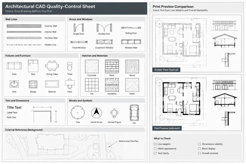
6. Make a plot-style test sheet
Create a small internal test drawing containing representative lines, hatches, text, dimensions, blocks, images, and xref content. Include examples of layer-controlled objects and deliberate property overrides. Review the resulting PDF at normal viewing size and on paper when printed output is part of the deliverable.
Coordinating Plot Styles with Xrefs and Imported Content
External references can expose weaknesses in a plotting system because consultant layers, colors, lineweights, and object properties may not match the architectural file. Inspect incoming DWG files before using them as production backgrounds. Do not assume that changing an xref layer color solves every output problem; objects inside the reference may contain overrides or nested content.
When a consultant background must be visually subdued, use a repeatable project method rather than editing the source file without coordination. Possible approaches include host-drawing layer overrides, controlled background layers, or a separate display configuration. The selected method should be tested in the final sheet context.
Blocks deserve similar attention. Geometry inside a block may be set to inherit insertion properties, follow internal layers, or retain explicit object properties. If a block prints incorrectly, inspect its internal construction before compensating with unrelated page-setup changes.
Common Plotting Problems and What to Check
- Everything prints with similar weight: Confirm that the correct table is selected, plotting with styles is enabled, and geometry uses the intended colors or named styles.
- One block prints too heavily: Inspect nested objects for explicit colors, lineweights, or plot-style assignments.
- An xref is darker than expected: Review xref layer properties, object overrides, nested references, and the background treatment used in the host file.
- The plot style is missing: Verify the support-file location and confirm that the drawing expects the same plot-style type as the available file.
- PDFs differ between users: Compare plot-style files, page setups, output settings, fonts, and other support resources rather than assuming the DWG alone controls the result.
- Screen appearance does not match the PDF: Remember that display colors are drafting aids. Use print preview and an actual PDF test to evaluate final output.
Quality-Control Checklist
- Confirm whether the drawing uses CTB or STB plot styles.
- Verify that all production layouts use the approved page setup.
- Check the plot-style file name and managed file location.
- Review cut elements, outlines, annotation, hatches, and backgrounds as a complete hierarchy.
- Inspect copied blocks and imported details for object-level overrides.
- Test consultant xrefs in the actual sheet viewports.
- Compare a representative PDF against the approved graphic standard.
- Avoid converting the plot-style system late in production unless there is a documented need and time for full review.
A Consistent System Matters More Than the Label
CTB and STB workflows can both support professional architectural documentation. CTB connects indexed colors closely to printed output, while STB uses explicit named plotting treatments. The best choice is the one that the project team can apply consistently across templates, layers, blocks, xrefs, page setups, and published sheets.
Whichever system is selected, document the logic, limit unnecessary overrides, maintain one controlled source for plot-style files, and test output throughout production. Plot styles should reinforce the architectural drawing hierarchy—not become a last-minute repair tool.
Evaluate the Workflow at the Sheet Level
A plot-style system should be judged by the resulting document set, not by isolated objects in model space. A wall, hatch, note, or consultant background may appear reasonable by itself while competing with other information in a completed sheet. Review plans, elevations, sections, details, and annotation together to confirm that the intended reading order remains clear.
Plot previews are useful for diagnosis, but the published PDF is the more meaningful coordination artifact. It reveals whether screening, lineweight, color conversion, raster content, and external references work together under the approved page setup.
Make Plotting Intent Transferable
A reliable standard should be understandable by someone who did not create it. For CTB projects, document what the drafting colors mean and how overrides affect output. For STB projects, define each named style by its graphic purpose and explain where assignments are expected to occur.
Project handoff information should identify the required plot-style type, the approved file, the page-setup logic, and any special treatment used for backgrounds or imported content. This reduces dependence on personal settings and helps distinguish a missing support resource from a problem inside the drawing.
Treat Conversion as a Coordination Task
Changing between CTB and STB affects more than the plot-style file. Layer properties, object overrides, block contents, external references, templates, and saved page setups may all reflect the original method. Conversion should therefore be performed on controlled copies and checked through representative sheets before the revised files enter production.
Do not assume that a visually acceptable preview proves that the conversion is complete. Inspect copied details, nested blocks, xrefs, hatches, dimensions, and annotation for assignments that may not follow the new plotting logic.
Keep Exceptions Deliberate
Property overrides are sometimes useful, but repeated exceptions usually indicate an unclear layer structure, an unsuitable block, or an incomplete plotting standard. Before overriding an object, determine whether the condition is unique or whether it represents a recurring graphic role that should be handled systematically.
The most maintainable workflow keeps the normal path simple: users select the appropriate layer and follow the established property rules. Exceptions are then limited, visible, and easier to audit.
Frequently Asked Questions
Can a CTB file be used directly in an STB drawing?
No. The drawing must use the plot-style system that matches the available table. Renaming a file or selecting the other file type does not translate the underlying assignments.
Does changing an object color always change its printed lineweight?
In a CTB workflow, changing an indexed color can change the plotted treatment defined by the table. In an STB workflow, display color and the assigned named plot style can be managed separately. Direct lineweight settings and other overrides must also be considered.
Why does a block plot differently from the layer on which it is inserted?
Objects inside the block may have explicit colors, lineweights, layers, or plot-style assignments. Nested blocks can add another level of inherited or fixed properties. Inspect the block definition before changing the page setup or plot table.
Why does an xref remain dark after its layer color is changed?
The reference may contain object-level overrides, nested references, internal layers, or properties that do not respond as expected to the host-layer change. Review the referenced content and test the chosen background treatment in the final viewport.
Should an office choose CTB or STB for all projects?
A shared office standard can simplify templates, support files, training, and quality control. However, project requirements, consultant coordination, client standards, and legacy content may justify maintaining a different established workflow. Consistency within each project remains essential.
What should be included when sending CAD files to another team?
Provide the coordinated drawing package together with the required plot-style file and clear information about page setups and plotting conventions. Confirm that external references and other necessary support resources are organized for the recipient’s workflow.
How can teams prevent PDFs from plotting differently on separate workstations?
Use a controlled plot-style file, coordinated page setups, and consistent support resources. When output differs, compare the complete publishing environment rather than checking only the DWG.