Elevator drafting is a multidisciplinary coordination task rather than a simple symbol-placement exercise. The shaft, landing openings, equipment references, structural interfaces, and architectural finishes must remain consistent across every affected view.
This guide explains a practical elevator CAD coordination workflow for organizing reference information, aligning plans and sections, managing repeated graphics, and checking the architectural drawing set. Project requirements and verified consultant or manufacturer information should always take precedence over generic blocks and assumptions.
Elevators occupy a relatively small area on a floor plan, but they connect architectural, structural, mechanical, electrical, life-safety, and accessibility information across multiple levels. A shaft adjustment on one floor can affect wall layouts, structural openings, door locations, equipment space, roof conditions, and interior finishes elsewhere in the drawing set.
Effective elevator CAD coordination is therefore less about drawing a generic elevator symbol and more about controlling information. The architectural drawings should clearly show the coordinated building conditions while distinguishing those conditions from equipment information supplied by an elevator consultant, manufacturer, or specialty contractor.
Start with verified project information
Do not size an elevator installation from an unverified CAD block. A downloaded block can be useful as a graphic placeholder, but it does not establish the required shaft, car, door, pit, overhead, support, or equipment conditions.
Before developing the drawings, collect the project information available from the design team. Depending on the project phase, this may include:
- The number and intended use of elevators.
- The floors or levels served by each unit.
- Preliminary or selected elevator system information.
- Consultant layouts and manufacturer planning documents.
- Structural framing and opening information.
- Door orientation and opening arrangement at each landing.
- Project-specific accessibility and life-safety criteria.
- Requirements for lobbies, equipment spaces, ventilation, power, controls, and communications.
Track whether each item is conceptual, design-development information, or verified installation data. This prevents a preliminary layout from being mistaken for a final requirement.
Establish a clear CAD information hierarchy
Separate architectural geometry from reference information. The shaft walls, finished lobby surfaces, floor openings, room boundaries, and architectural dimensions normally belong in the architectural model. Equipment outlines and clearance information received from another party should remain identifiable as reference or consultant content.
A practical file may distinguish among the following information:
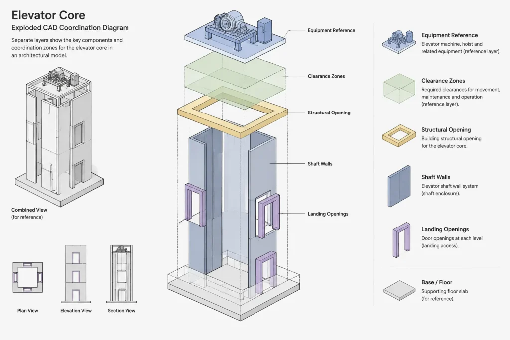
- Architectural shaft walls and wall type tags.
- Elevator landing doors and frames.
- Structural opening or slab-edge references.
- Elevator car and equipment outlines.
- Clearance or reserved zones.
- Pits, overhead spaces, and equipment rooms or cabinets.
- Power, communication, ventilation, and control references.
- Notes, dimensions, levels, and detail callouts.
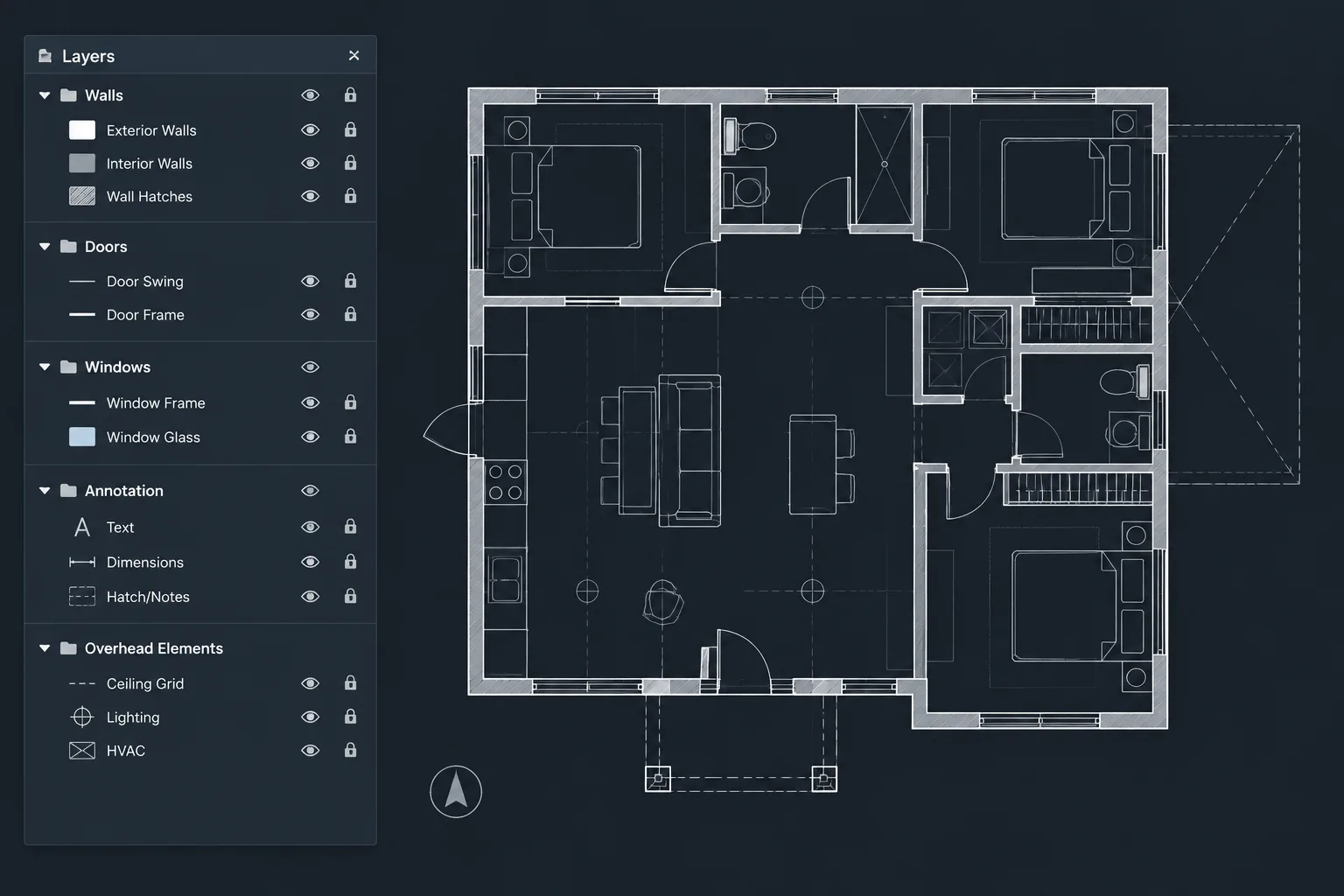
Use the project layer standard rather than creating isolated layer names for one drawing. Reference files should be attached using the project’s established origin, units, and path practices. Avoid copying consultant geometry into multiple floor-plan files unless there is a controlled reason to do so.
Draft the shaft as a coordinated vertical element
Treat the elevator shaft as one vertical building element, not as unrelated rectangles drawn independently on each floor. Begin from a controlled reference point, such as the project grid or a stable shaft corner, and align every served level to that location.
Check the shaft on all relevant plans, including levels where the elevator does not open. Wall construction, offsets, adjacent rooms, and structural conditions may change even when the shaft remains vertically aligned.
Show the plan condition clearly
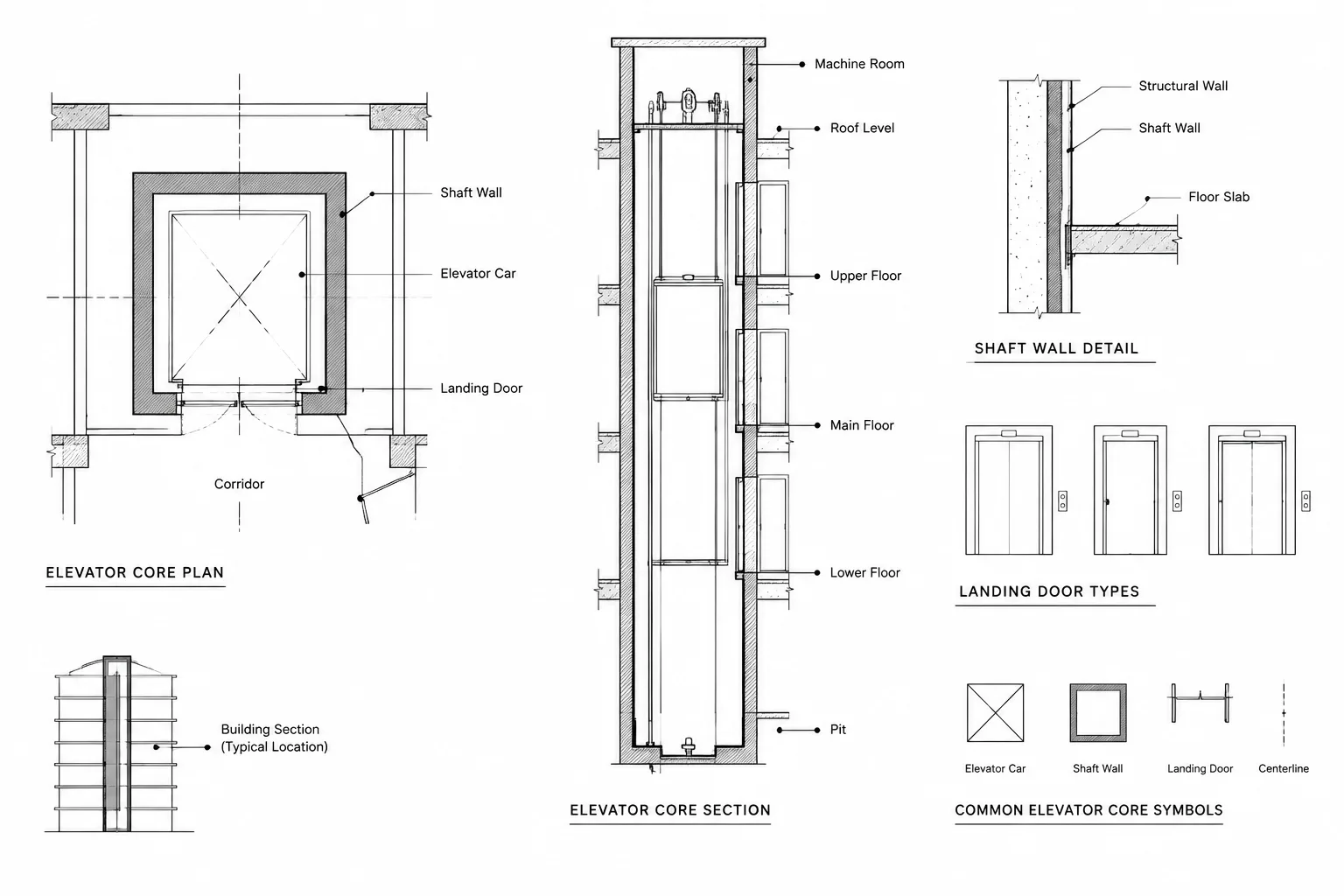
At each landing, the plan should communicate the shaft enclosure, landing opening, adjacent lobby or corridor, and surrounding construction. The car outline may be shown when it helps explain the arrangement, but it should not compete graphically with the architectural cut elements.
Use lineweight and linetype hierarchy to distinguish:
- Walls and components cut by the plan plane.
- Visible surfaces beyond the cut plane.
- Equipment shown for coordination.
- Overhead or concealed conditions.
- Clearance and reserved zones that are not physical objects.
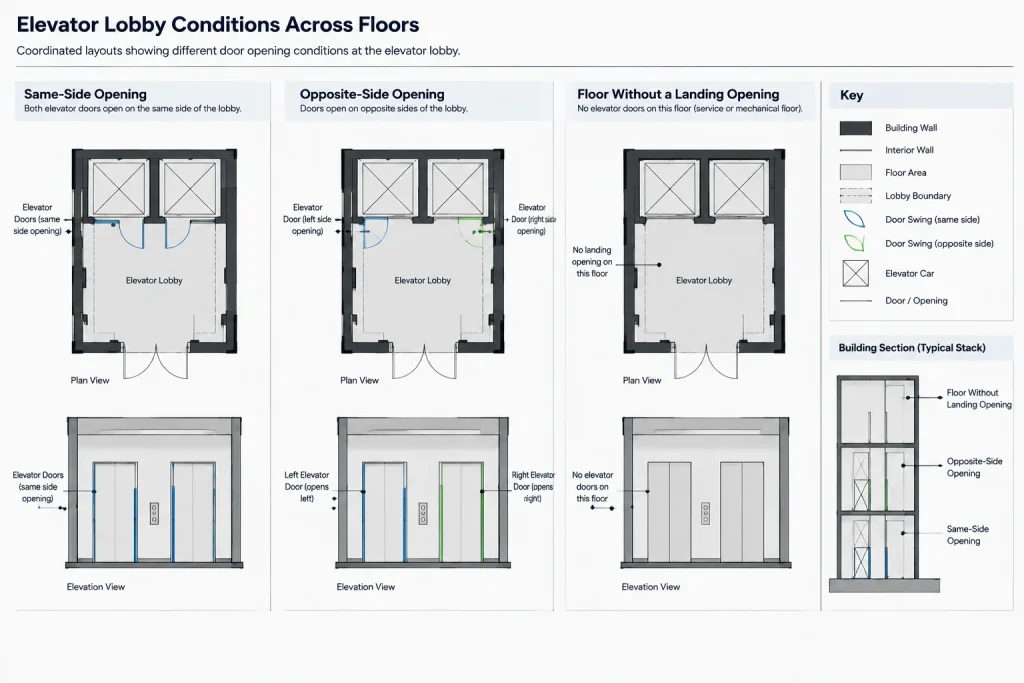
If the door arrangement changes by floor, do not rely on a single typical plan without documenting the exceptions. Opposite-side openings, different lobby configurations, or floors without a landing opening should be represented correctly.
Coordinate plans, sections, and elevations together
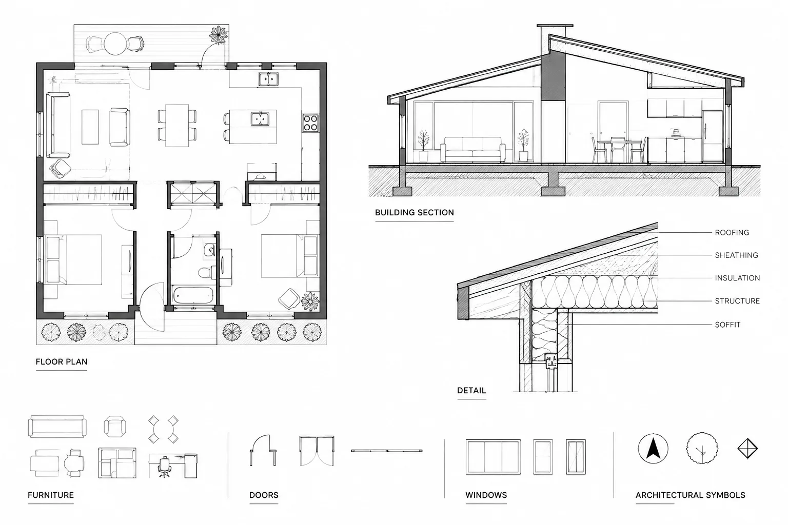
A plan alone cannot explain an elevator installation. Create at least one coordinated vertical view where the project documentation requires it. A section can show the relationship among floor levels, landings, shaft limits, pit, top condition, openings, and nearby roof or equipment spaces.
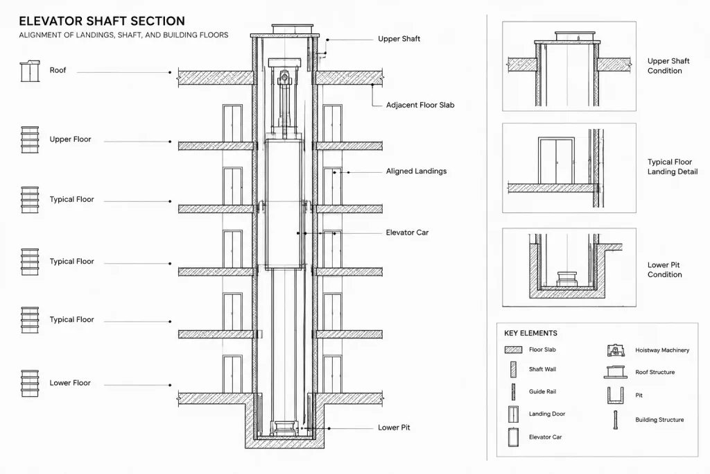
Develop the section from the same floor levels used throughout the architectural set. Do not manually enter unrelated elevation text if associative or centrally controlled level information is available within the project workflow.
Review the following relationships in section:
- Finished floors and structural slabs.
- Landing openings at every served level.
- The lowest shaft and pit condition.
- The upper shaft and overhead condition.
- Roof framing, drainage, and nearby rooftop construction.
- Equipment spaces and access routes.
- Structural beams, slabs, and foundations around the shaft.
- Openings or sleeves required for coordinated building services.
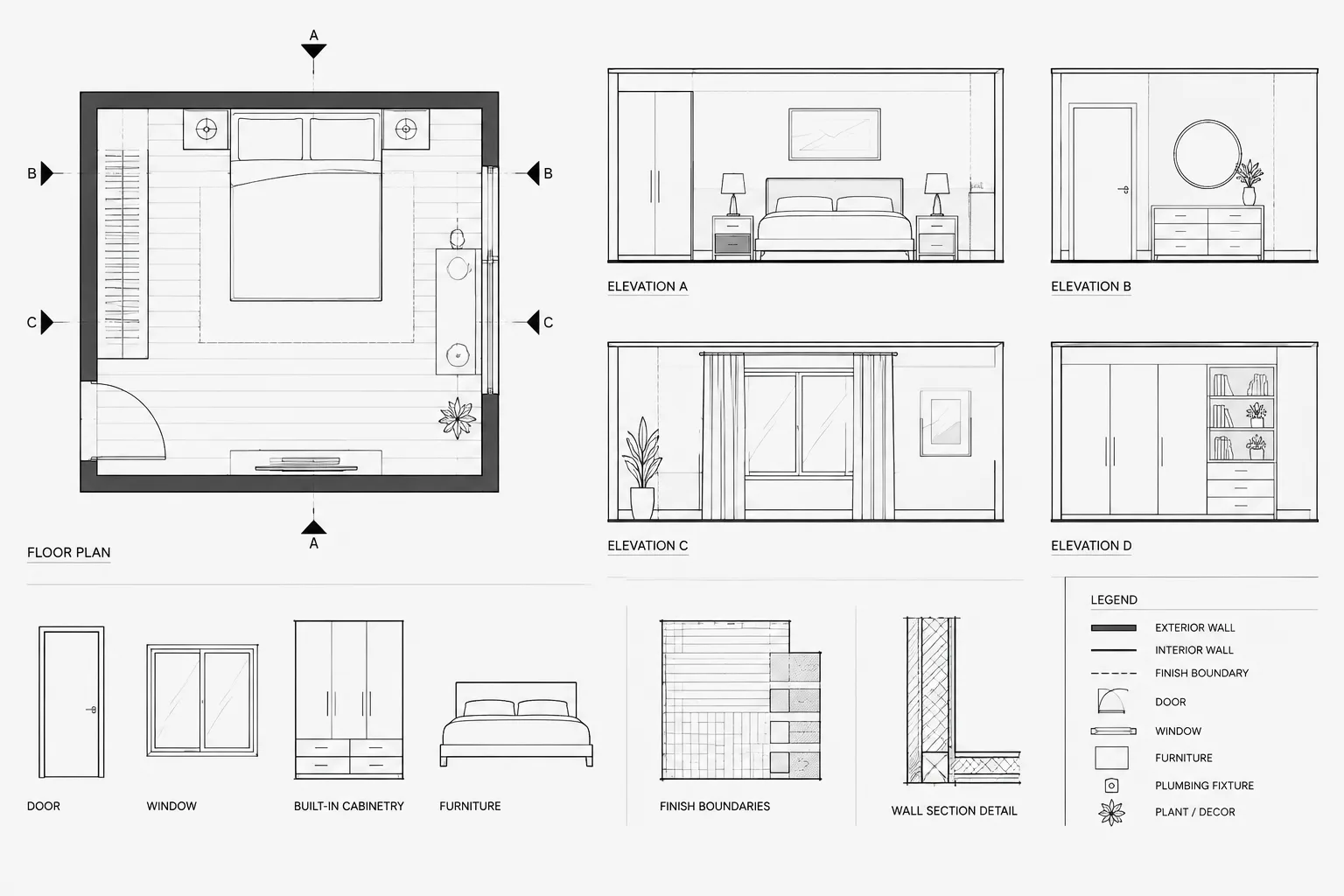
Interior or lobby elevations may also be necessary to document door frames, finishes, call buttons, indicators, signage, base conditions, and adjacent wall features. Dimensions and mounting information should come from verified project criteria rather than a generic elevation block.
Define responsibility for each drawing item
Elevator documents often contain overlapping information from several disciplines. A simple responsibility matrix can prevent duplication and contradiction.
| Drawing item | Typical coordination question | CAD handling |
|---|---|---|
| Shaft walls | What construction and finish boundaries apply? | Keep controlled architectural geometry tied to wall types and plans. |
| Structural openings | Who establishes slab, beam, and foundation limits? | Reference structural information and flag unresolved differences. |
| Elevator equipment | Is the layout preliminary or verified? | Retain source identification and avoid redrawing it as architectural fact. |
| Landing doors | Do opening orientation and frame conditions vary? | Coordinate plans, elevations, details, and schedules. |
| Controls and signals | Who specifies location, interface, and mounting criteria? | Show coordinated locations only after design-team review. |
| Service connections | Where are power, communication, ventilation, or drainage interfaces? | Use consultant references and coordinated callouts rather than assumptions. |
The exact division of responsibility varies by contract and project. The matrix is a coordination aid, not a substitute for the project requirements.
Use blocks carefully for repeated graphics
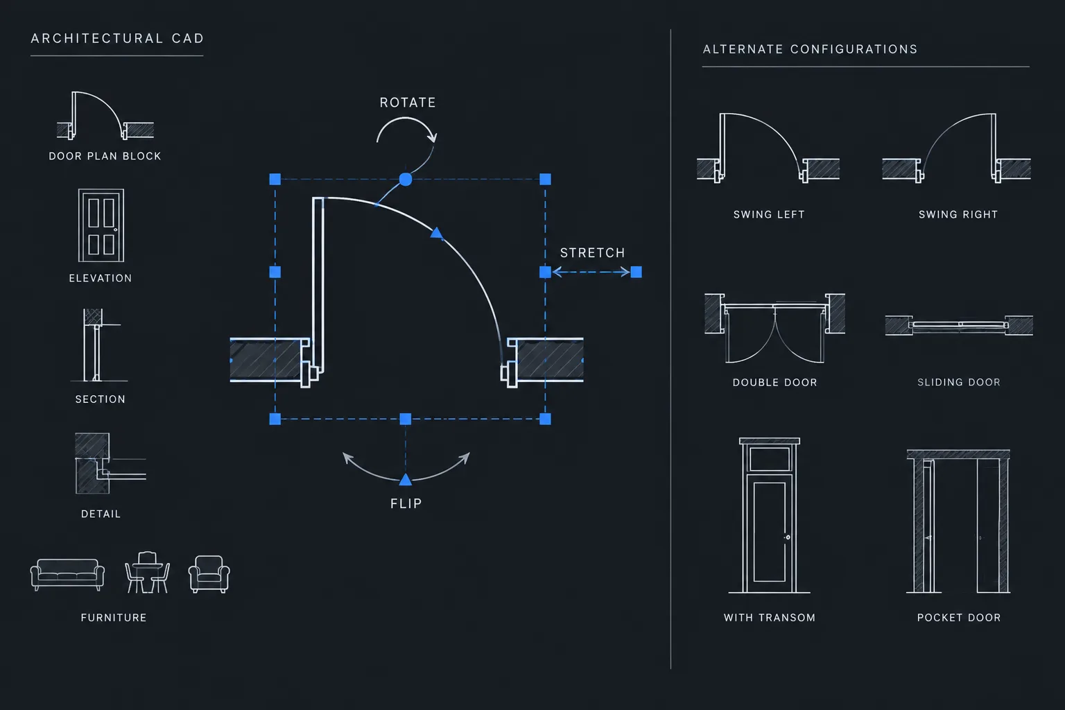
Blocks can help maintain consistent car outlines, door symbols, identifiers, and annotation. However, avoid creating one universal elevator block that hides important variation. Different floors may have different openings, wall depths, lobby finishes, or adjacent construction.
If a block includes attributes, use them for controlled identifiers such as elevator designation or served-floor notes. Keep project-specific dimensions outside the block when they need to remain visible and independently checked. Do not scale an equipment block non-uniformly to force it into an uncoordinated shaft; obtain the correct layout instead.
Coordinate related architectural drawings
Elevator information should agree across the entire drawing set. Review it against:
- Overall and enlarged floor plans.
- Building and wall sections.
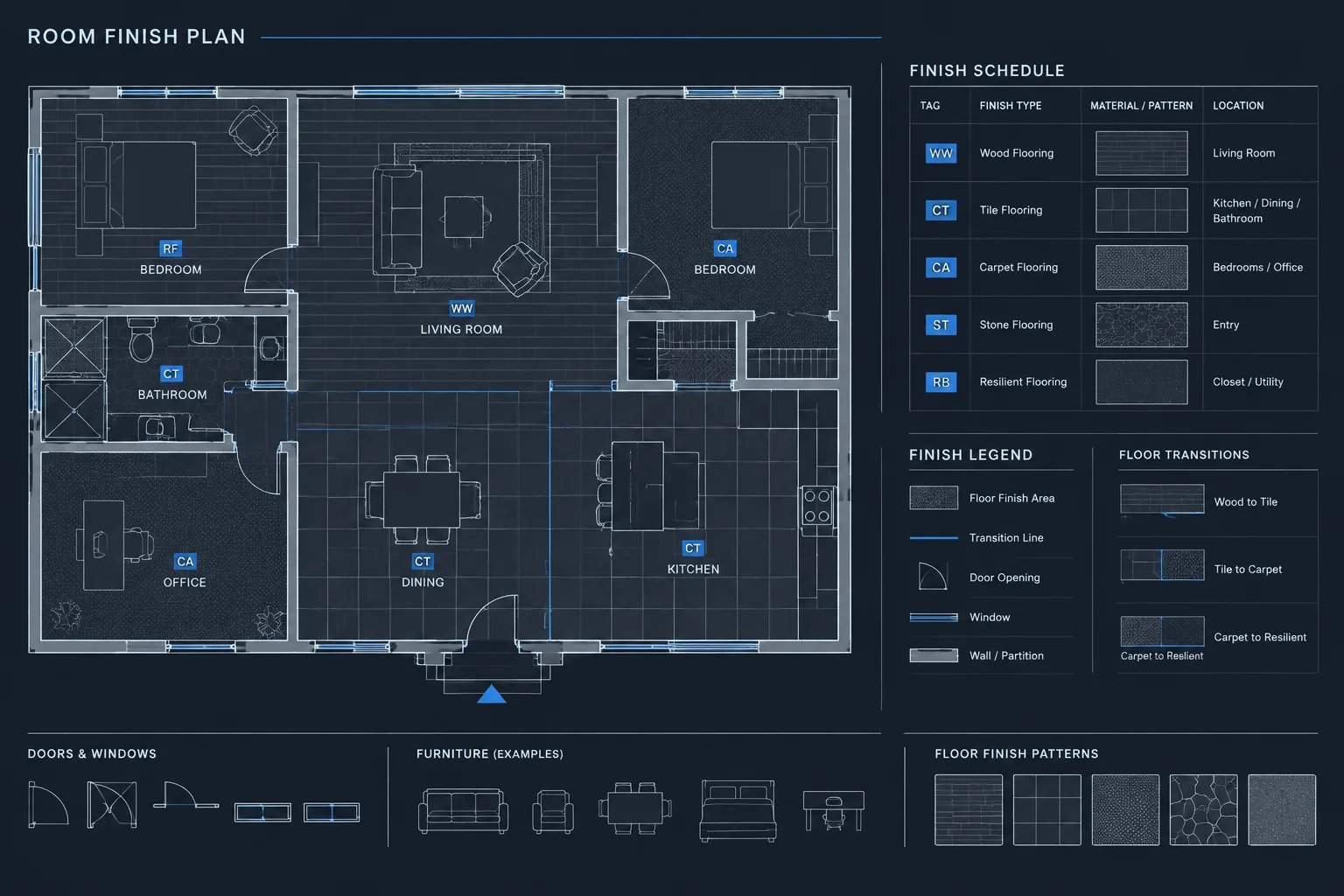
- Interior elevations and finish plans.
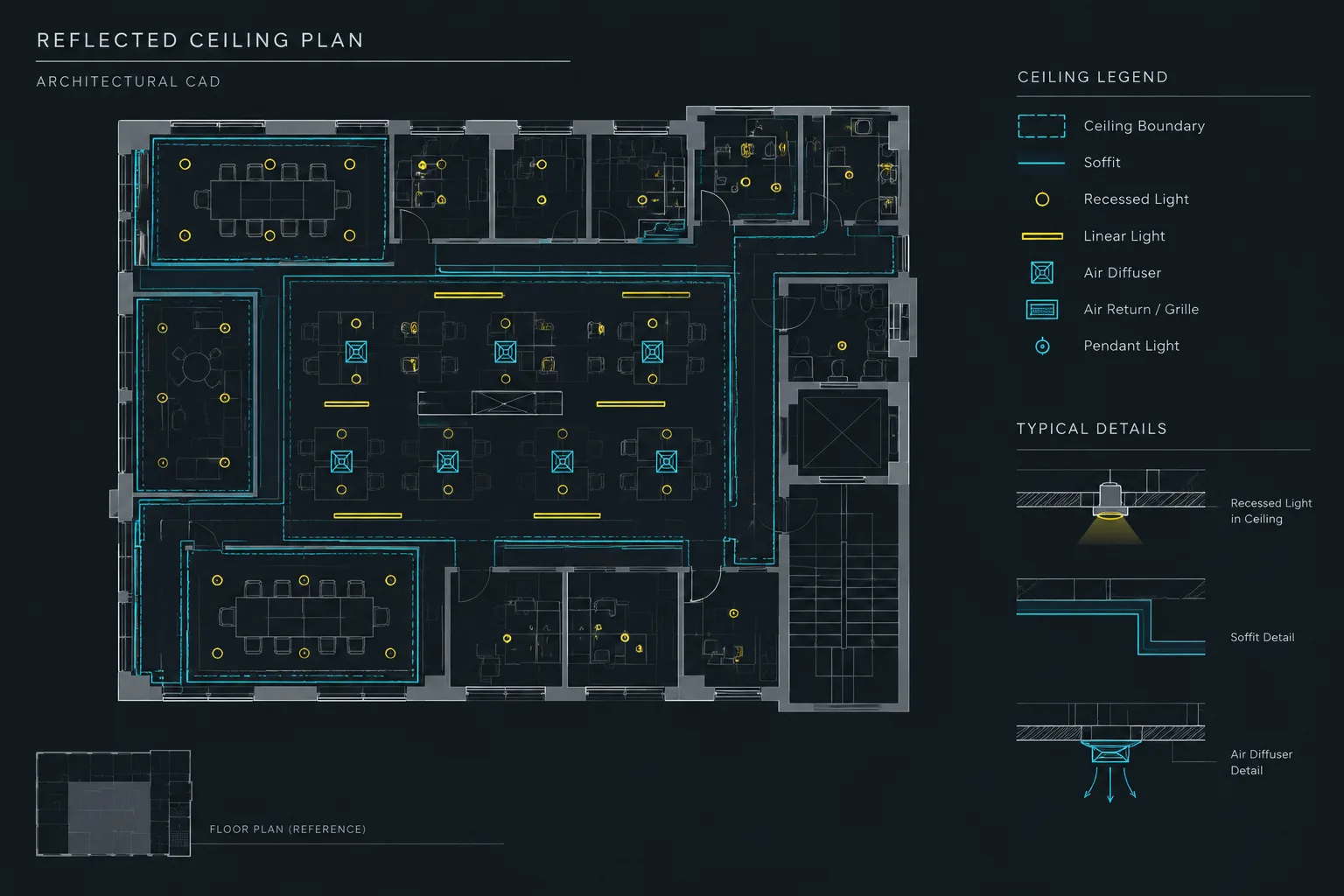
- Reflected ceiling plans at lobbies.
- Door, opening, and finish schedules where applicable.
- Structural plans and details.
- Electrical, mechanical, plumbing, fire-protection, and communication drawings.
- Roof plans and below-grade plans.
- Life-safety and accessibility documentation.
Pay special attention to elements immediately outside the elevator entrance. Ceiling grids, lighting, sprinklers, signs, floor patterns, wall joints, and call stations can conflict visually or physically even when the shaft itself is correct.
Run a focused elevator CAD quality check
Before an issue, isolate the elevator-related layers and references, then review each level in sequence. A focused check should confirm that:
- The shaft aligns vertically from the lowest to the highest relevant level.
- Every landing opening matches the current elevator information.
- Door orientation is consistent among plans, elevations, and consultant layouts.
- Plans and sections use the same floor levels.
- Pit and top-of-shaft conditions are represented where required.
- Wall types and finishes do not unintentionally reduce reserved equipment space.
- Structural edges and openings agree with the architectural background.
- Reference files are current, visible, and correctly positioned.
- Preliminary equipment is labeled appropriately and not presented as verified construction information.
- Dimensions have clear origins and do not create conflicting control points.
- Callouts lead to the correct sections, elevations, and details.
Finally, review the plotted sheets rather than relying only on model-space inspection. Confirm that equipment references remain legible, clearance zones do not overpower the plan, and the architectural construction hierarchy is clear at the published scale.
Maintain a traceable coordination record
When updated elevator information arrives, record its source and date according to the project workflow. Compare it with the previous layout, identify meaningful changes, and update every affected drawing rather than only replacing the visible plan reference.
A disciplined elevator CAD coordination process keeps architectural geometry authoritative, consultant information traceable, and unresolved criteria visible. That approach produces drawings that are easier to review and reduces the risk of a small shaft change creating inconsistencies throughout the project set.
Use a change-impact workflow
Elevator revisions should be reviewed as drawing-set changes, not isolated plan edits. When the shaft, landing opening, equipment arrangement, or adjacent construction changes, identify every view and schedule that may carry related information before updating the files.
Classify the change before drafting
- Architectural change: A revision to walls, finishes, openings, room boundaries, lobby configuration, or drawing annotation.
- Consultant change: Updated equipment geometry, clearance information, interfaces, or planning criteria received from the responsible source.
- Coordination change: A revision caused by structural framing, building services, roof construction, ceilings, or adjacent spaces.
- Documentation change: A correction to callouts, identifiers, levels, schedules, references, or graphic hierarchy without changing the underlying design.
This classification helps the team determine who should verify the revision and which CAD content remains authoritative.
Follow the change through the drawing set
Begin with the controlled shaft location and compare the revised information against each relevant level. Continue through enlarged plans, vertical views, lobby elevations, ceiling information, schedules, details, and consultant backgrounds. Where a conflict remains unresolved, show its status through the project’s established coordination method rather than quietly adjusting another discipline’s geometry.
After updating the model or drawing files, inspect the published sheets. A technically correct reference can still become unclear if linework is screened too lightly, clearance graphics obscure architectural elements, or an outdated annotation remains visible in a dependent view.
Separate graphic convenience from design authority
A CAD block, copied detail, or previous project file can speed up drafting, but it should not become the source of project criteria. Use reusable content for consistent graphics while maintaining a clear distinction between a drawing aid and verified installation information.
That distinction is especially important when a placeholder resembles a finished equipment layout. Label preliminary content appropriately, retain its source identity, and replace or revise it through a traceable review process when confirmed information becomes available.
Frequently Asked Questions
Can a generic elevator CAD block be used to size a shaft?
No. A generic block may support early graphic studies, but shaft and equipment conditions should come from verified project information supplied or reviewed by the responsible design participants.
Should elevator equipment be drawn directly into the architectural file?
The architectural file should control architectural construction. Equipment geometry from consultants, manufacturers, or specialty contractors is generally clearer when it remains identifiable as referenced information rather than being redrawn as architectural fact.
How should floors without an elevator opening be documented?
Show the actual condition at each level. The shaft may continue through a floor even when no landing door is present, and the surrounding walls, structure, rooms, and services still require coordination.
Why should the elevator be reviewed in section as well as plan?
Sections reveal relationships that plans cannot fully communicate, including floor levels, the lower shaft condition, the upper shaft condition, structural interfaces, landing alignment, and nearby roof or equipment spaces.
What should be checked when updated elevator information arrives?
Confirm the source and status of the update, compare it with the previous information, identify affected views and disciplines, revise dependent drawings, and inspect the resulting sheets for conflicting geometry or annotation.
How can blocks remain useful without hiding floor-to-floor differences?
Use blocks for genuinely repeated graphics and controlled identifiers. Keep variable openings, wall conditions, finishes, and project-specific dimensions visible and independently coordinated rather than forcing every floor into one universal block.