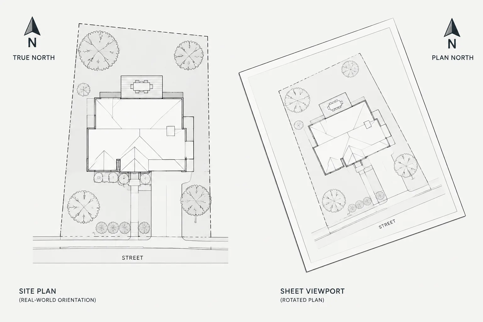
Architectural CAD orientation is easier to manage when location, drafting direction, and sheet presentation are treated as separate decisions. A plan can appear upright in a viewport even though the model remains aligned with verified project coordinates, and a north arrow must communicate the direction applicable to that specific view.
Before changing geometry, determine whether the apparent problem belongs to the model, the current working view, an attached reference, or the paper-space viewport. That distinction helps prevent a presentation adjustment from becoming a coordination error.
North orientation can become surprisingly complicated in an architectural CAD project. A building may be modeled according to survey coordinates, displayed square to the screen for efficient drafting, and placed on a sheet at a different rotation for readability. If those choices are not documented, users may rotate geometry unnecessarily, misalign external references, or place a misleading north arrow.
A reliable workflow separates three ideas: the real-world direction of north, the working orientation used to draw the building, and the rotation used to compose a sheet. Treating these as related but distinct controls helps preserve coordinate accuracy while keeping plans easy to read.
Understanding the orientation terms
True north
True north is a geographic direction. On a project using survey information, its graphic direction should come from the verified survey or another approved project reference. It should not be estimated from an aerial image, a street edge, or the top of an imported PDF.
True north is especially relevant when coordinating site information, solar orientation, property geometry, civil backgrounds, and other location-based data. A north arrow identifies direction, but it does not establish the drawing’s coordinate system by itself.
Plan north
Plan north is the direction treated as “up” or another convenient reference direction on architectural plans. It may also be called project north or drawing north, depending on office terminology. The purpose is practical: a building that is diagonal in real-world coordinates can be shown square to the sheet, making walls, dimensions, text, and details easier to organize.
Plan north is a drafting convention rather than a substitute for verified geographic orientation. When plan north differs from true north, the distinction should be clear in the drawing set.
Model coordinates
Model coordinates define where geometry exists in the DWG environment. On a coordinated project, these coordinates may be based on a shared project origin, a survey system, or an agreed local coordinate framework. Changing the screen view does not need to change these coordinates.
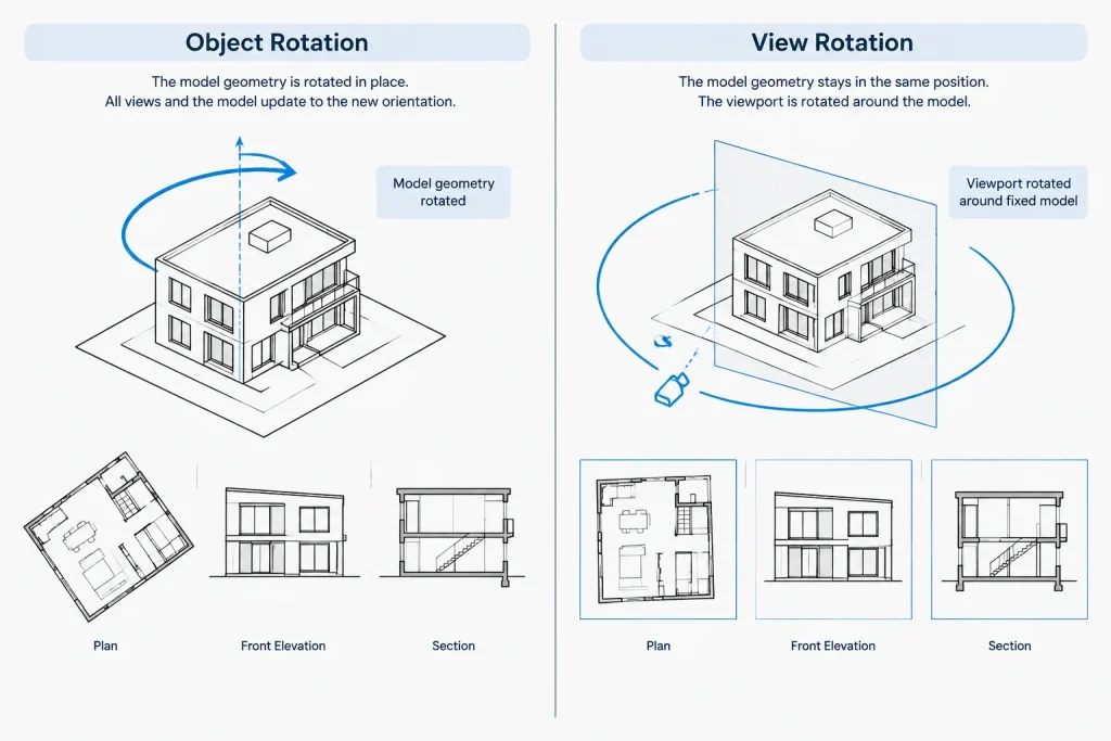
This is a critical distinction: rotating a view is not the same as rotating the model. View rotation changes how geometry is displayed. Object rotation changes the geometry itself and may disrupt xref alignment.
Choose an orientation strategy early
The project team should decide how the architectural model will relate to survey and consultant files before substantial drafting begins. There are two common approaches.
| Approach | Advantages | Coordination concerns |
|---|---|---|
| Model in shared real-world orientation | Supports direct alignment with survey, civil, landscape, and other location-based references | The building may appear diagonal in model space and require controlled view rotation for drafting and sheets |
| Model square to a documented local orientation | Simplifies orthogonal drafting and day-to-day navigation | Requires a reliable transformation or agreed insertion method when exchanging files with coordinate-based disciplines |
Neither method should be adopted informally. The correct choice depends on the project’s exchange requirements, consultant workflow, office standards, and source data. What matters most is that the team uses one documented method consistently.
Do not rotate coordinated geometry just to improve sheet composition
A common mistake is to rotate the building, site plan, or attached backgrounds because the plan does not fit neatly on a sheet. This may make one layout look better while causing wider coordination problems. Previously aligned xrefs can shift, insertion assumptions can become unreliable, and updated consultant files may no longer land correctly.
When the model coordinates are already established, solve sheet orientation with a rotated view or viewport instead of rotating the source objects. This preserves the relationship between architectural geometry and external references.
Before rotating any coordinated model objects, confirm:
- Which file establishes the project location and orientation.
- Whether consultants expect shared coordinates or a documented local origin.
- Whether attached files are positioned by common coordinates or manual insertion.
- Whether existing sheets, details, and references depend on the current orientation.
- Who has authority to approve a project-wide coordinate change.
A practical CAD workflow
Establish the source orientation
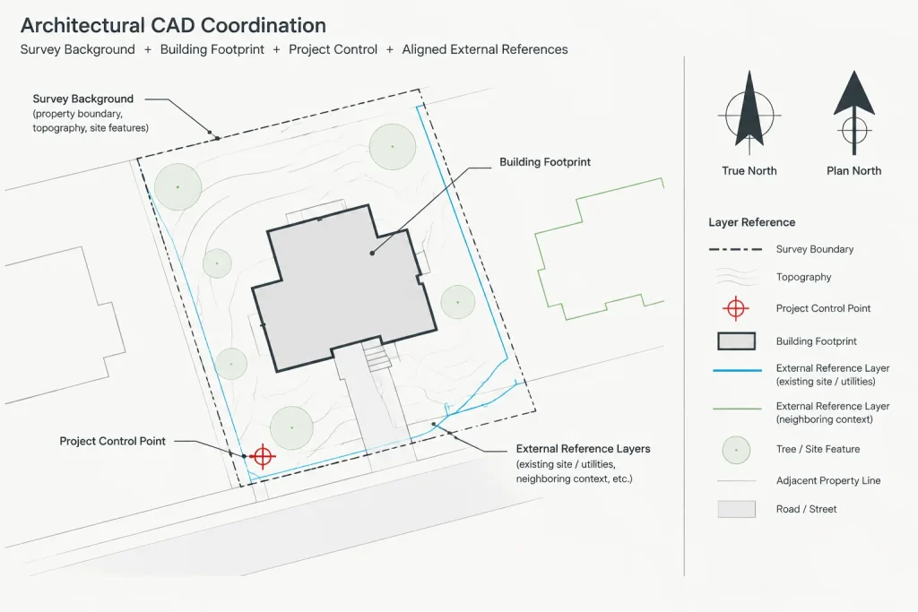
Begin with the most reliable project reference, typically verified survey or civil information when geographic orientation is required. Confirm units, insertion point, rotation, and scale before using that file as a base. Record the source and any agreed transformation in the project CAD notes.
Keep base geometry stable
Once the project origin and orientation are accepted, avoid moving or rotating the main backgrounds casually. Lock or otherwise protect reference layers where appropriate, and use a repeatable xref insertion method. Reattaching an updated file should not require visual realignment by eye.
Create a working view
If the building is diagonal in model coordinates, create a view that makes its primary walls convenient to draft. AutoCAD allows the user coordinate system and the displayed plan view to be aligned for a working orientation. This can make orthogonal drafting easier without changing the underlying object positions.
Use named views or an office-approved setup so other users can return to the same orientation. Avoid leaving an unexplained temporary coordinate system active when saving a shared file.
Compose sheets with viewport rotation
In paper space, orient each plan through its viewport. The building can be presented square to the sheet while remaining unchanged in model coordinates. After setting the view, confirm its scale and lock the viewport to prevent accidental panning, zooming, or rotation.
Do not assume every sheet must use the same rotation. Overall plans, enlarged plans, site plans, and partial plans may require different compositions. However, changing orientation between related sheets should be intentional and clearly communicated.
Place annotation in the correct context
Text and dimensions should read consistently within the selected annotation workflow. Model-space annotation may need to follow the plan’s working orientation, while paper-space sheet notes normally follow the sheet. Mixed workflows require additional review because text can appear rotated correctly in one viewport but incorrectly in another.
Using north arrows correctly
A north arrow should describe the orientation of the view in which it appears. If a floor plan is rotated square to the sheet, a true north arrow may point diagonally. If the project also uses plan north, label the symbols clearly rather than relying on subtle graphic differences.
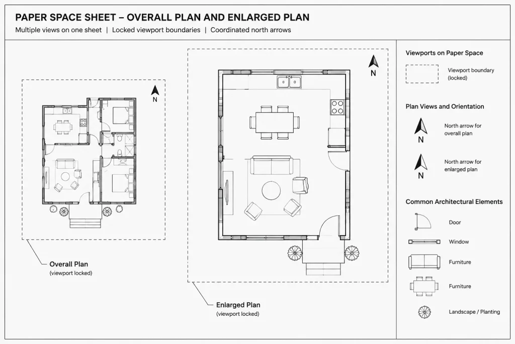
North arrows should be checked independently on site plans, floor plans, enlarged plans, and key plans. Copying one symbol across layouts without reviewing each viewport can produce incorrect directions.
A good north-arrow review asks:
- Is the arrow intended to show true north or plan north?
- Is that meaning labeled clearly?
- Does the arrow respond correctly to the viewport rotation?
- Does it agree with the verified survey or project orientation reference?
- Is the symbol placed in model space or paper space, and is that placement intentional?
Coordinating xrefs and consultant files
Orientation problems often become visible when new consultant backgrounds arrive. If an updated xref appears rotated or displaced, do not immediately drag it into place. Compare its insertion settings, units, base point, coordinate assumptions, and path to those of the previous file.
Maintain a simple exchange test location that is recognizable across disciplines, such as a documented grid intersection or project control point. This provides a more reliable check than comparing an irregular wall edge. The test point does not replace survey control, but it can quickly reveal whether files share the intended relationship.
When issuing a background, tell recipients whether the geometry is in shared coordinates, local project coordinates, or another documented orientation. A north arrow alone is not enough information for accurate file placement.
Common orientation failures
- Rotating geometry for every sheet: Multiple versions of the same plan begin to disagree and cannot share references reliably.
- Using the screen direction as north: A convenient display orientation is mistaken for geographic orientation.
- Rotating an xref by eye: The file appears close enough visually but no longer matches the controlled project position.
- Leaving a temporary UCS active: Another user opens the file and drafts in an unexpected direction.
- Placing a static north arrow: The arrow remains unchanged after the viewport is rotated.
- Using inconsistent terminology: “North,” “project north,” and “plan north” are used interchangeably without a project definition.
Orientation quality-control checklist
- Confirm the approved project origin and orientation source.
- Verify that base files and xrefs align without manual visual adjustment.
- Separate model-coordinate decisions from sheet-composition decisions.
- Check saved working views and coordinate-system settings.
- Lock completed viewports after setting view direction and scale.
- Review annotation readability in every rotated view.
- Verify each north arrow against its specific viewport.
- Compare plans, key plans, elevations, and site drawings for consistent directional references.
- Document any coordinate transformation used for file exchange.
Keep orientation controlled, not merely convenient
A clear north-orientation workflow allows the model to remain coordinated while sheets remain readable. The central rule is simple: preserve verified geometry and coordinates, then control presentation through working views and paper-space viewports. When true north, plan north, and view rotation are explicitly defined, teams can exchange DWG files with fewer alignment errors and review architectural plans with greater confidence.
Diagnosing an orientation problem before editing
When a plan appears rotated or an external reference no longer aligns, first identify where the discrepancy occurs. If the geometry is correct in model space but looks wrong on a sheet, investigate the viewport and saved view. If only one attached file is displaced, review that reference’s insertion assumptions rather than rotating the architectural model. If geometry aligns but text is difficult to read, the issue may be annotation orientation rather than project coordinates.
A useful troubleshooting sequence is to compare stable project control geometry, inspect the active coordinate and view settings, review the affected viewport, and then check the north-arrow context. Avoid correcting several of these elements at once, because simultaneous changes make it difficult to identify the original cause.
Record orientation decisions for file handoff
A coordinated DWG should be accompanied by clear project information describing the accepted origin, model orientation, meaning of plan north, and expected reference insertion method. The notes should also distinguish permanent project settings from working views created for drafting convenience.
This information is particularly important when files move between architectural, civil, landscape, structural, and other project teams. A recipient should not need to infer coordinate intent from the visible angle of a building or from a north symbol alone.
Review orientation as part of sheet quality control
Orientation review should include more than checking whether the plan fits attractively on the sheet. Confirm that related views communicate direction consistently, annotations remain readable, key plans agree with the displayed area, and every north arrow represents the view where it is placed. When a sheet uses a different orientation from nearby plans, make that change deliberate and visually understandable.
Frequently asked questions
Are plan north and true north the same?
Not necessarily. True north represents verified geographic direction, while plan north is a drafting convention used to organize and read the plan. They may coincide, but they should be treated as separate concepts unless the project documentation confirms otherwise.
Does rotating a CAD view change model coordinates?
A controlled view rotation changes how geometry is displayed rather than where the objects exist. Rotating the objects themselves is a different operation and can affect alignment with external references and consultant files.
Should a north arrow be placed in model space or paper space?
Either approach can be used within a documented office workflow. The important requirement is that the symbol correctly describes its specific view and remains accurate when the viewport orientation changes. Mixed placement methods deserve careful review.
Why does an updated xref appear rotated or displaced?
Possible causes include different coordinate assumptions, insertion settings, base points, units, or an undocumented change in the incoming file. Compare the new reference with the established exchange method before moving or rotating it by eye.
Must every plan sheet use the same orientation?
No. Different plan types or enlarged areas may require different sheet compositions. However, orientation changes should be intentional, clearly communicated, and checked against the relevant north arrow, key plan, and related views.
Can a north arrow establish shared coordinates?
No. A north arrow communicates direction but does not define an origin, insertion point, or coordinate framework. File exchange still requires documented coordinate and placement information.