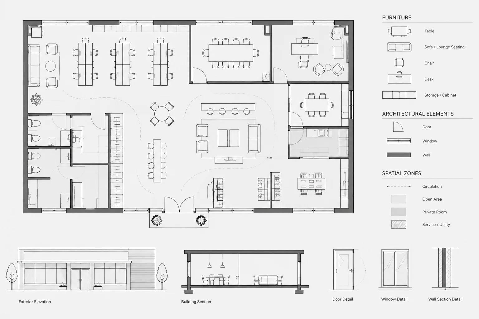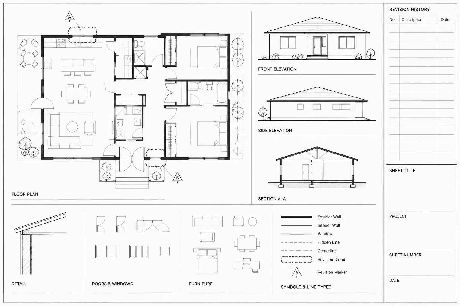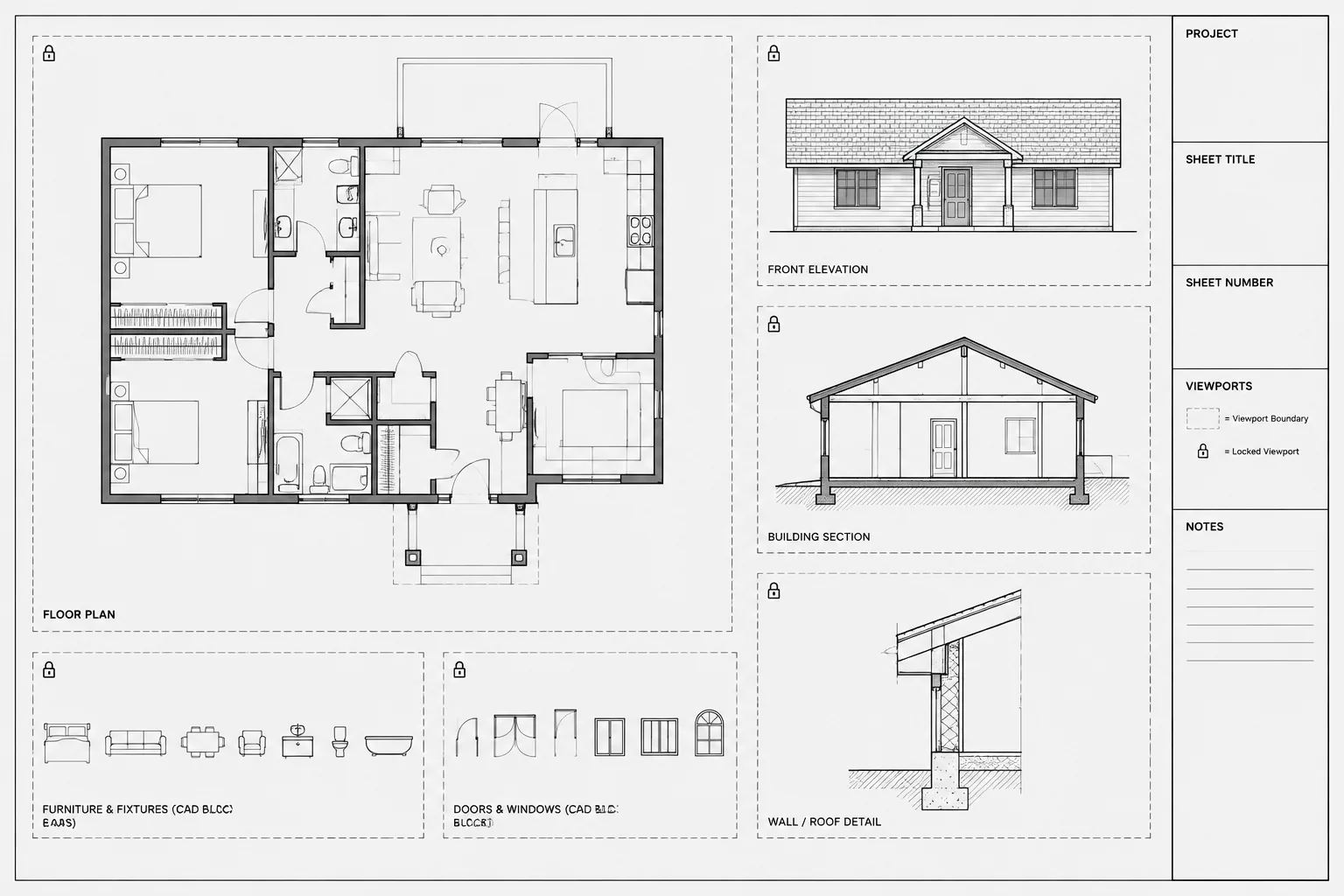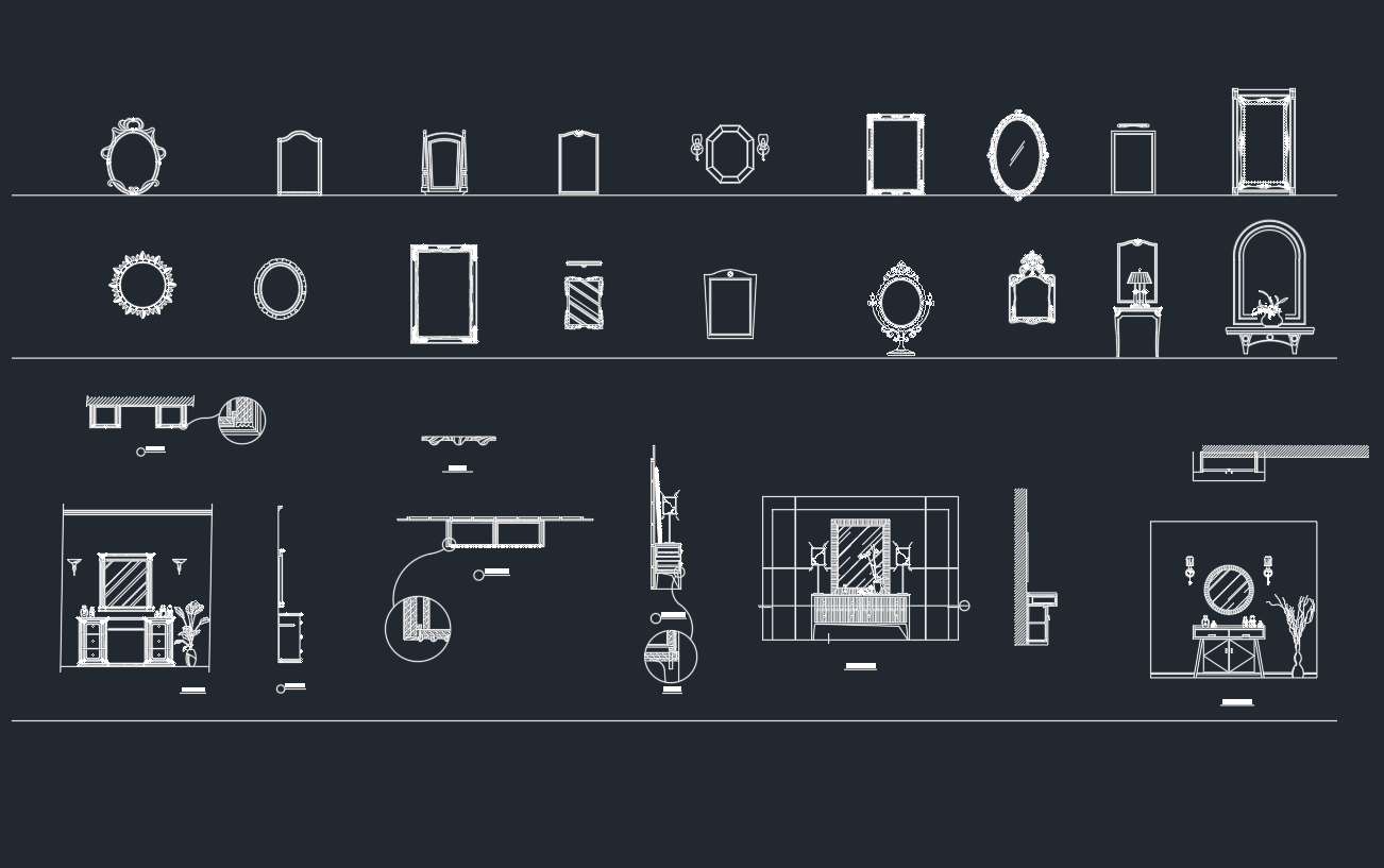
Mirrors CAD blocks help communicate mirror locations and design intent in interior plans, elevations, and related architectural drawings. A reusable DWG resource can reduce repetitive drafting while supporting consistent graphic presentation across bathrooms, bedrooms, dressing areas, hallways, and other interior spaces.
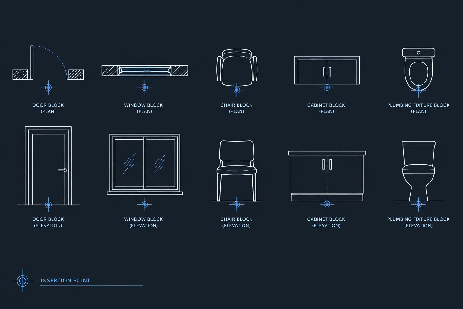
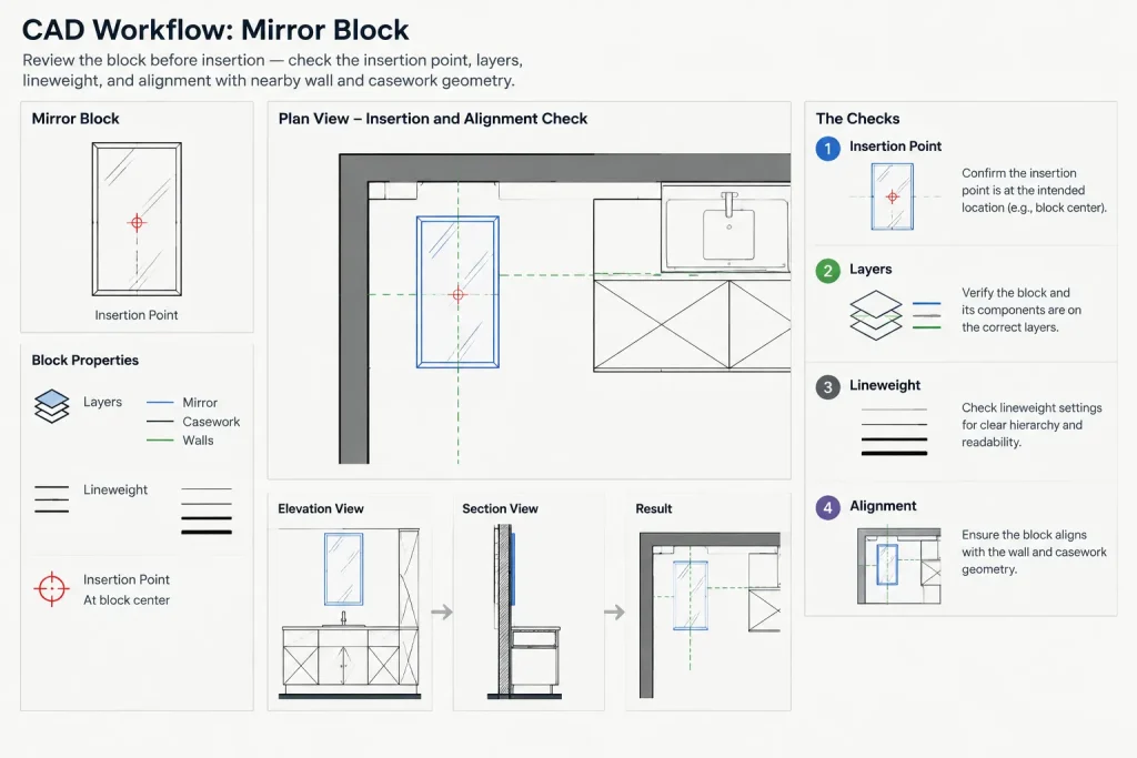
Before adding any mirror block to a drawing set, review its view orientation, drawing units, insertion point, layer structure, and level of detail. The geometry should be adjusted to match the selected product, surrounding construction, and documentation requirements rather than treated as a verified project specification.
Discover a high-quality DWG file CAD Block of mirrors, perfect for architects, interior designers, and engineers working on residential or commercial projects. This detailed CAD Block includes various mirror designs and styles, making it easy to incorporate into your AutoCAD drawings. Enhance your layouts with accurate mirror representations for bathrooms, bedrooms, hallways, and more. The DWG file is fully compatible with AutoCAD and other CAD software, ensuring seamless integration and easy customization. Download this versatile mirrors CAD Block to streamline your design process and create visually appealing, professional floor plans.
Please log in or register to download this file.
How to Use Mirror DWG Blocks
Start by opening or previewing the downloaded file separately from the project drawing. This makes it easier to inspect the available mirror designs, remove unnecessary objects, identify the intended view, and confirm that the geometry behaves as expected.
When inserting a mirror block, place it in relation to the wall, vanity, countertop, casework, or other nearby elements. Avoid positioning it only by visual judgment. Its location should coordinate with the project layout and with any applicable mounting, accessibility, electrical, finish, and interior-design information.
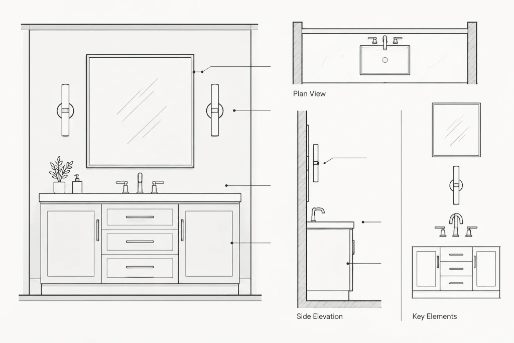
Plan and Elevation Representation
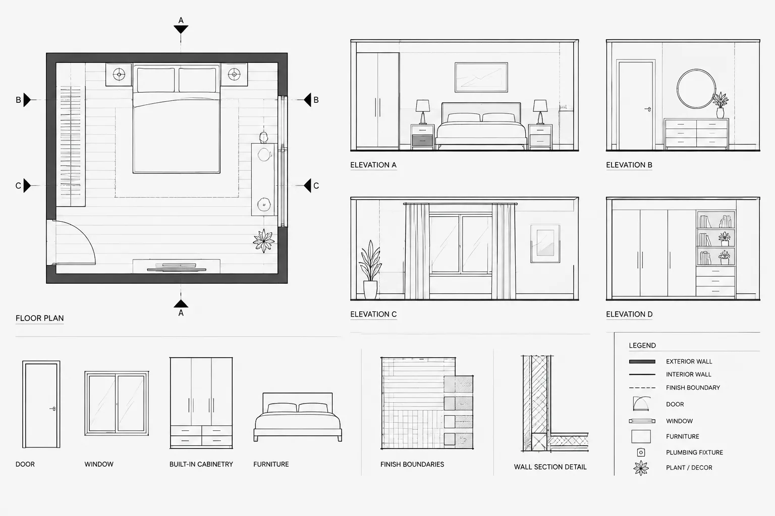
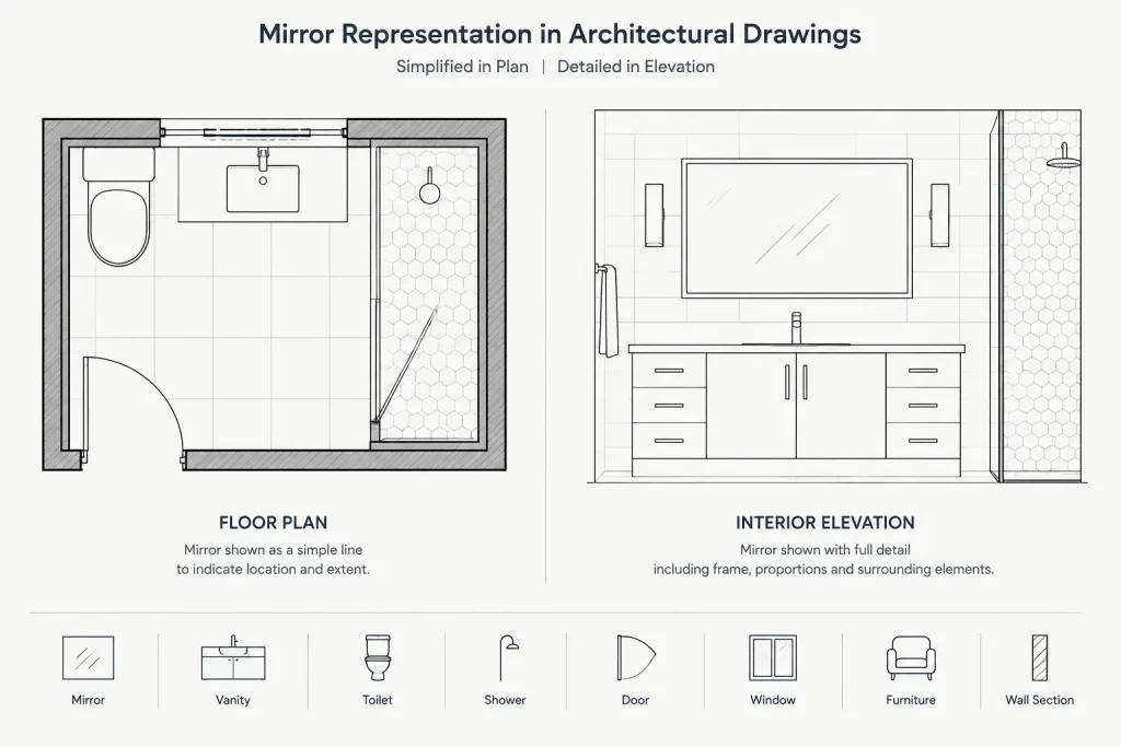
A mirror may require different graphic treatment depending on the drawing view. In a floor plan, it may be represented with restrained linework near the wall or fixture it serves. In an interior elevation, its outline, shape, frame, and relationship to adjacent finishes can be shown more directly. Confirm what each supplied block represents before using it in a particular view.
Scale and Unit Checks
Do not assume that downloaded geometry uses the same units or scale conventions as the destination file. Compare the block with known project geometry before relying on its apparent size. Scale or redraw it as needed to match verified product information and the intended installation.
Layers and Graphic Clarity
Place mirror geometry on layers that follow the project’s CAD standards. Review object colors, linetypes, lineweights, and nested layers so the block plots consistently with the rest of the sheet. Simplified outlines are often clearer than decorative reflection lines, especially at smaller drawing scales.
Mirror Block Review Checklist
- View: Determine whether the geometry is intended for a plan, elevation, section, or presentation drawing.
- Units: Compare the block with verified project geometry before scaling or placing it.
- Insertion point: Choose a logical reference point that supports accurate alignment with walls, vanities, or casework.
- Layers: Move objects to approved project layers and remove unwanted nested layer assignments.
- Detail: Simplify excessive curves, hatches, or decorative lines when they reduce legibility.
- Coordination: Check the mirror against fixtures, lighting, accessories, finishes, and adjacent openings.
- Annotation: Use project-specific tags, notes, or schedules rather than relying on text embedded in a generic block.
Related Drawing Resources
Mirror symbols are commonly coordinated with bathroom CAD blocks, vanity layouts, plumbing fixtures, interior elevations, furniture blocks, lighting symbols, and architectural annotation. Reviewing these related drawing categories can help keep placement, labeling, and graphic conventions consistent throughout a project set.
Frequently Asked Questions
Can a mirror CAD block be used without editing?
It should be reviewed before use. Check its size, units, view, layers, insertion point, and graphic detail against the destination drawing and verified project information.
Should mirrors appear in both plans and elevations?
That depends on the drawing purpose and documentation scope. Plans can communicate location, while elevations can show shape and alignment with nearby fixtures or finishes. Separate view-specific symbols may provide clearer documentation.
How should a mirror block be aligned?
Use relevant project references such as wall faces, fixture centerlines, casework edges, or finish extents. The correct reference depends on the design intent and the information available for the selected mirror.
Why does an inserted DWG block appear at the wrong size?
The source and destination drawings may use different unit conventions, or the block may have been created for another drafting context. Compare it with known geometry and correct the scale before incorporating it into the project.
Can these blocks define the final mirror specification?
No generic CAD block should replace verified product data or project documentation. Confirm the required shape, dimensions, frame, mounting method, finish, and coordination conditions separately.
Quick Questions About Mirrors CAD Blocks
What should be checked after downloading the DWG?
Inspect the available designs, drawing units, layers, insertion points, object complexity, and intended views before copying geometry into a working file.
How can mirror symbols remain legible when plotted?
Use clear outlines, controlled lineweights, and limited decorative detail. Test the block in the actual sheet context and simplify any geometry that becomes visually cluttered.
What other CAD content is useful when laying out mirrors?
Bathroom fixtures, vanities, casework, lighting symbols, interior elevations, finish information, and annotation resources provide useful coordination context.