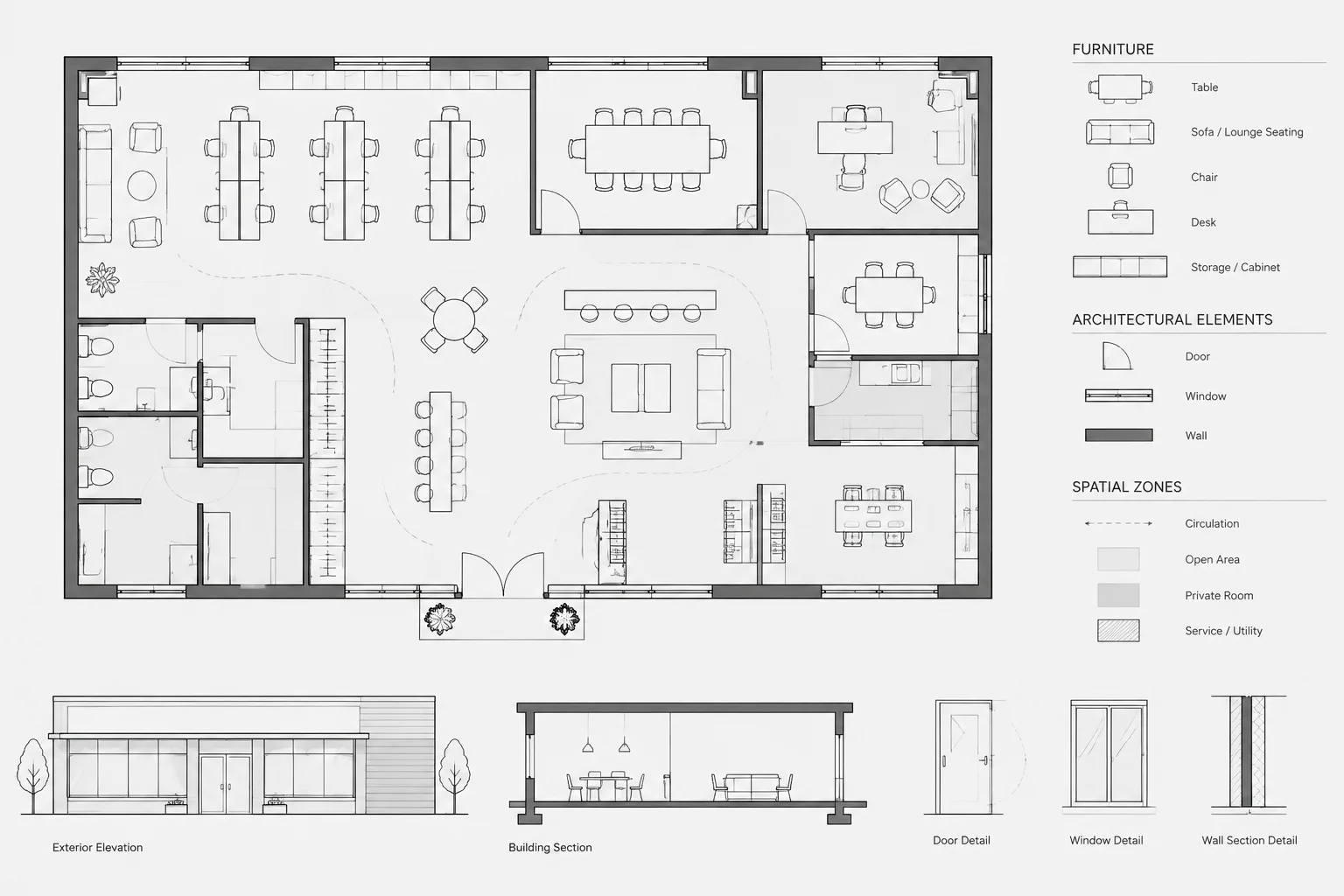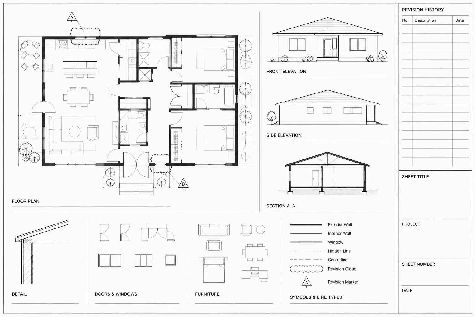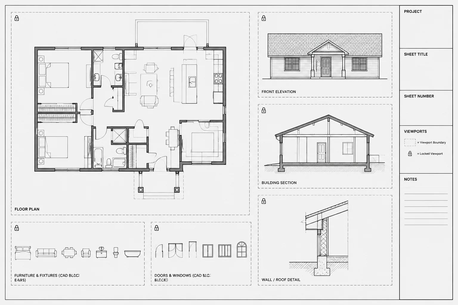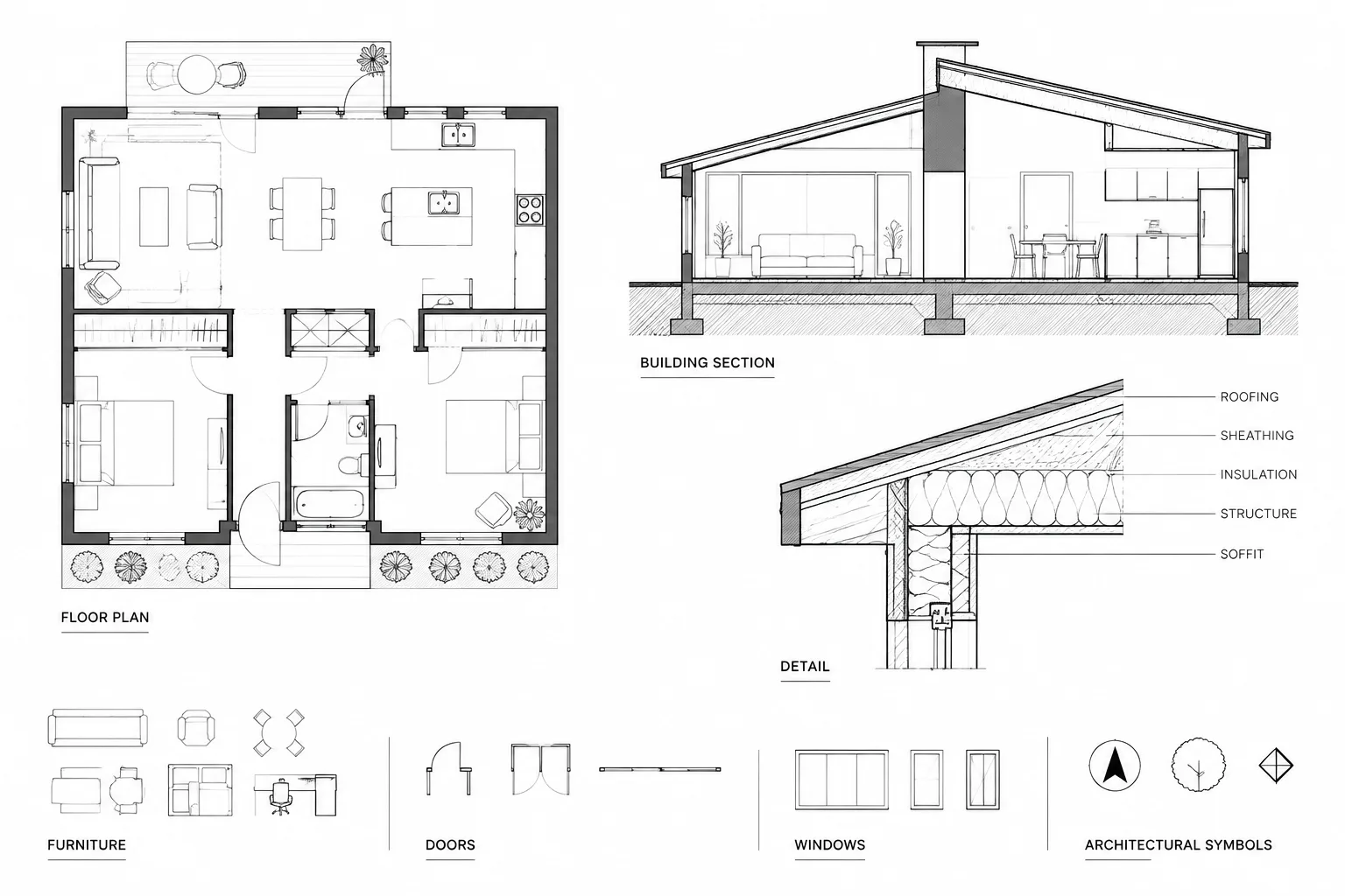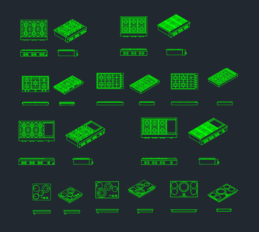
A cooktop CAD block provides a reusable appliance symbol for developing kitchen plans and coordinating the cooking area with countertops, cabinets, sinks, and circulation space. The DWG resource below can support early layout studies as well as more developed architectural drawings.
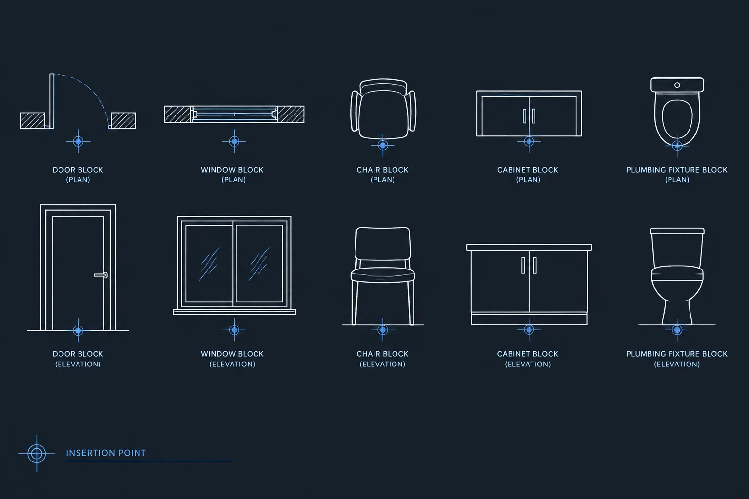
Before using the block in a project, review its drawing units, geometry, insertion point, layers, and available views. The represented appliance dimensions should be checked against the selected manufacturer’s current documentation rather than treated as installation requirements.
Discover a high-quality Cooktop DWG file, perfect for architects and interior designers seeking precise kitchen layout solutions. This detailed CAD Block offers accurate dimensions and realistic detailing, making it ideal for integrating into residential or commercial kitchen plans. Compatible with AutoCAD and other leading CAD software, the Cooktop DWG file ensures seamless workflow and easy modifications. Use this resource to enhance your kitchen designs, streamline your drafting process, and achieve professional results in your architectural or engineering projects. Download now for efficient, reliable kitchen planning.
Please log in or register to download this file.
How to Use the Cooktop CAD Block
Insert the DWG into a working kitchen plan and first confirm that its scale matches the project file. Position the cooktop in relation to the countertop and base cabinets, then review nearby work areas, circulation paths, and other appliances. If the block contains more detail than the drawing requires, simplify its visible linework without altering the verified appliance footprint needed for coordination.
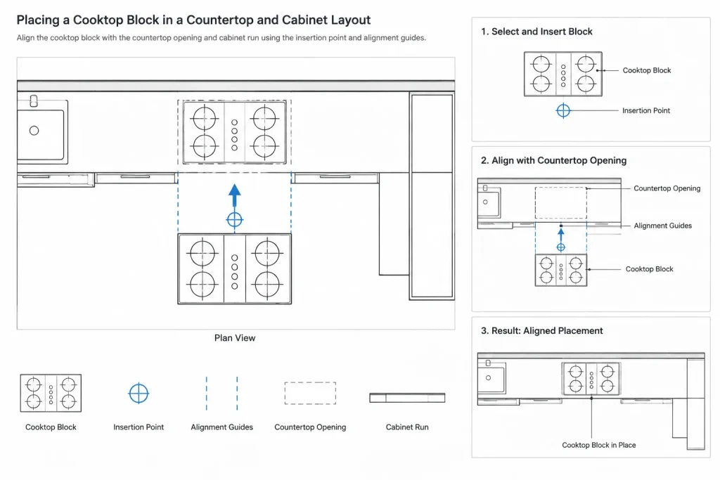
Coordinate the Block With the Kitchen Layout
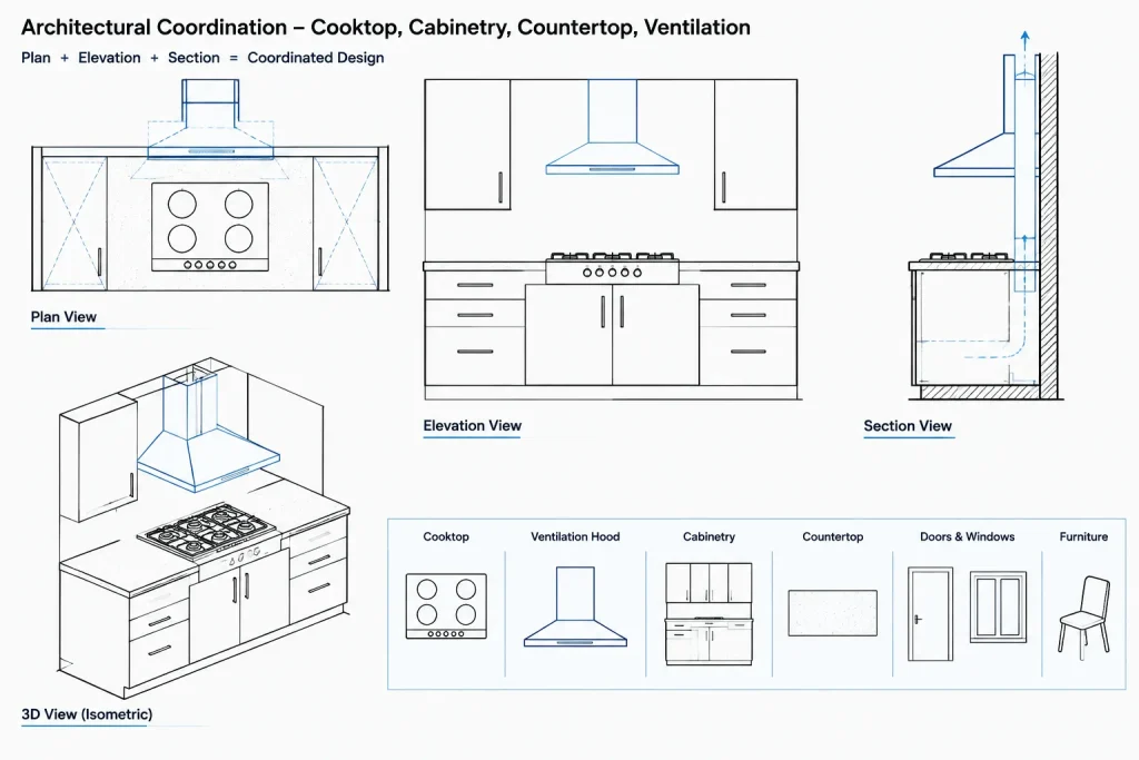
A cooktop is generally coordinated as a countertop-mounted appliance rather than as a complete range with an integrated oven. That distinction affects how the symbol relates to cabinetry, countertop openings, ovens, ventilation equipment, and elevations. The CAD block can establish a graphic location, but it does not replace product-specific installation information.
- Countertop and cabinet coordination: Check the selected product documentation before defining an opening, cabinet modification, or support condition.
- Ventilation: Coordinate the cooking location with the intended ventilation strategy and any applicable project requirements.
- Utilities: Confirm utility type and connection planning with the appliance information and relevant consultants.
- Drawing consistency: Match the block’s lineweights, colors, layers, and level of detail to the surrounding kitchen CAD blocks.
- Annotations: Keep appliance tags and notes separate from reusable geometry when that suits the office drafting standard.
DWG Review and Cleanup Workflow
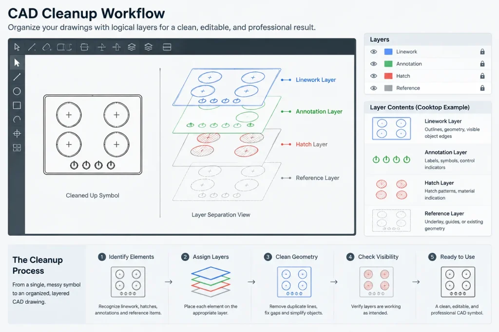
Open or inspect the downloaded file before adding it to a production drawing. Look for duplicate geometry, unnecessary fills, remote objects, inconsistent layer names, and text that may not apply to the project. Confirm the insertion point is practical for alignment with cabinets or countertops, and retain an untouched copy of the original file before editing.
For coordinated documentation, compare the plan symbol with related kitchen elevations and sections. A plan-view block communicates location and footprint, while elevations and sections are better suited to showing relationships with countertops, cabinets, wall finishes, and ventilation elements. Related resources such as kitchen cabinet CAD blocks, countertop details, sink blocks, appliance symbols, and architectural annotation guides can help create a more consistent drawing set.
Verification Before Construction Documents
Generic CAD geometry is most useful for planning and graphic communication. Product selection may change during design, and different cooktops can require different openings, supports, connections, and surrounding conditions. Replace or revise generic geometry when a specific appliance is approved, and verify all critical information against current manufacturer documentation and project requirements.
Frequently Asked Questions
What is a cooktop CAD block used for?
It is used to represent a cooktop in kitchen drawings, helping designers coordinate the appliance with countertops, cabinets, adjacent fixtures, and the overall room layout.
How do I know whether the DWG is drawn at the correct scale?
Check the file’s drawing units and measure the block after insertion. Compare its geometry with the intended appliance documentation before relying on it for detailed coordination.
Can the block define the countertop cutout?
Do not assume that the visible outline represents a required countertop opening. Cutout and support information should come from the selected manufacturer’s current installation documents.
What should I check before adding the block to a project file?
Review the units, insertion point, layers, linework, object properties, annotations, and overall extents. Remove irrelevant content and align the cleaned block with the project’s CAD standards.
Is a cooktop block the same as a range block?
No. A cooktop typically represents a cooking surface coordinated with a countertop, while a range generally combines the cooking surface and oven in one appliance. Use the symbol that matches the planned equipment.
Can this block be used as an installation detail?
A generic block should be treated as a planning and drafting resource, not as a substitute for appliance installation instructions, consultant coordination, or project-specific review.