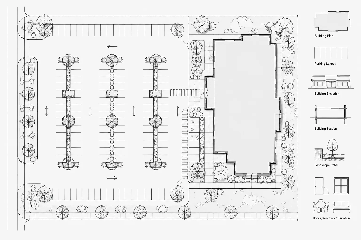
Drafting a parking lot layout in architectural CAD is an exercise in site coordination, not simply a matter of copying stall lines. The drawing must relate parking geometry to vehicle circulation, pedestrian access, building entrances, landscape areas, drainage, utilities, lighting, signs, and other site constraints.
The workflow below explains how to organize and review this information while keeping project criteria traceable. Because parking and accessibility requirements depend on the governing jurisdiction and project conditions, dimensions and classifications should come from verified project sources rather than generic CAD blocks or unconfirmed templates.
A parking plan is more than a repeated row of vehicle blocks. It must coordinate circulation, pedestrian movement, accessible routes, curbs, landscape areas, drainage, lighting, signs, utilities, and building entrances. A layout can look orderly in CAD while still containing conflicts that make it difficult to build or use.
This workflow explains how to develop a parking lot layout in architectural CAD without relying on unverified default dimensions. Parking requirements vary by jurisdiction, project type, vehicle mix, and governing criteria, so stall sizes, aisle widths, accessible provisions, fire access, setbacks, and counts should always be checked against the project’s verified requirements.
Begin with a controlled site background
Start from the best available civil or survey background rather than drawing parking geometry in an isolated file. Confirm that the reference uses the project coordinate system, drawing units, and current property information. At minimum, the working background should identify the elements that can constrain the layout:
- Property lines, easements, setbacks, and rights-of-way
- Existing and proposed buildings
- Curbs, sidewalks, driveways, and roadway connections
- Topographic information and known drainage structures
- Utilities, utility structures, and protected access zones
- Landscape areas and trees designated to remain
- Site walls, fences, gates, and service equipment
Keep consultant information as an external reference when possible. This allows the parking plan to respond to revised grading, utility, or site geometry without copying and maintaining a second version of the same information.
Collect the design criteria before drawing rows
Create a short project criteria note or worksheet before testing layouts. The purpose is not to reproduce code language, but to record which verified values control the drawing. Relevant inputs may include parking counts, stall categories, aisle criteria, accessible parking distribution, bicycle parking, loading needs, landscape requirements, fire department access, and electric vehicle provisions.
Label each value by source and status. For example, distinguish a confirmed jurisdictional requirement from an owner preference or an early planning assumption. This prevents a temporary design value from being mistaken for an approved criterion later in the project.
Organize the CAD file by function
A parking drawing is easier to revise when objects are separated by purpose. The exact layer names should follow the project standard, but useful categories generally include:
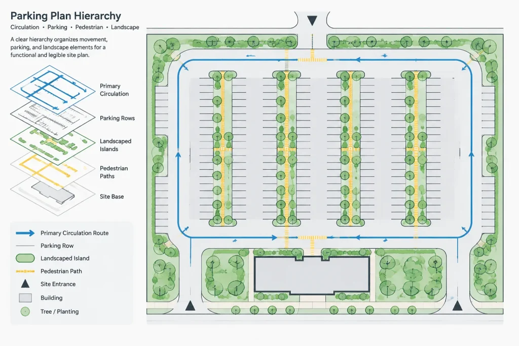
| Drawing content | Why it should be separate |
|---|---|
| Parking striping | Allows striping to be edited, counted, and plotted independently. |
| Curbs and islands | Separates constructed edges from painted markings. |
| Parking symbols and labels | Supports visibility control and annotation changes. |
| Pedestrian routes | Makes crossings, walks, and route continuity easier to review. |
| Vehicle templates | Keeps design checks distinct from final site graphics. |
| Landscape coordination | Helps identify conflicts between planting areas and vehicle movement. |
| Reference geometry | Contains temporary offsets, guide lines, and planning envelopes. |
Use temporary construction geometry deliberately. Guide lines should be placed on a nonplotting or clearly identified working layer so they do not appear accidentally on issued sheets.
Establish circulation before individual stalls
Lay out the primary vehicle path first. Identify site entrances, exits, internal intersections, drop-off areas, service access, and connections to parking fields. This circulation framework usually has more influence on the final plan than any individual parking row.
Use polylines to represent curb lines and major pavement edges. Polylines are easier to offset, measure, and revise than collections of unrelated line segments. Where the plan includes curves, check that curb returns connect cleanly and do not contain short fragments or accidental kinks.
Determine whether each aisle is intended for one-way or two-way movement, then make the stall orientation consistent with that decision. Avoid using arrows merely as graphic decoration; circulation arrows should communicate an intentional path that remains understandable at decision points.
Build a reliable parking module
A parking module is the repeatable relationship among stalls, striping, wheel stops or curb edges, and the adjacent drive aisle. Construct the module from verified project criteria rather than scaling a generic parking block until it appears correct.
A practical CAD method is to draw one stall bay accurately, including its boundary logic, and then repeat it with copy or array tools. Keep painted lines separate from reference envelopes. The reference envelope represents the space reserved for a vehicle, while the striping shows what will actually be marked in the field. Confusing these two can produce incorrect counts or inconsistent end conditions.
If angled parking is used, define the row direction and angle once and maintain that orientation throughout the parking field. Mirroring a module may change how vehicles enter and leave the row, so check the circulation direction after every mirrored operation.
Use blocks without hiding critical geometry
Blocks can help standardize parking symbols, directional arrows, signs, wheel stops, and representative vehicles. They should not obscure the actual curb and striping geometry used for documentation. Use a consistent insertion point and orientation so symbols can be replaced or updated efficiently.
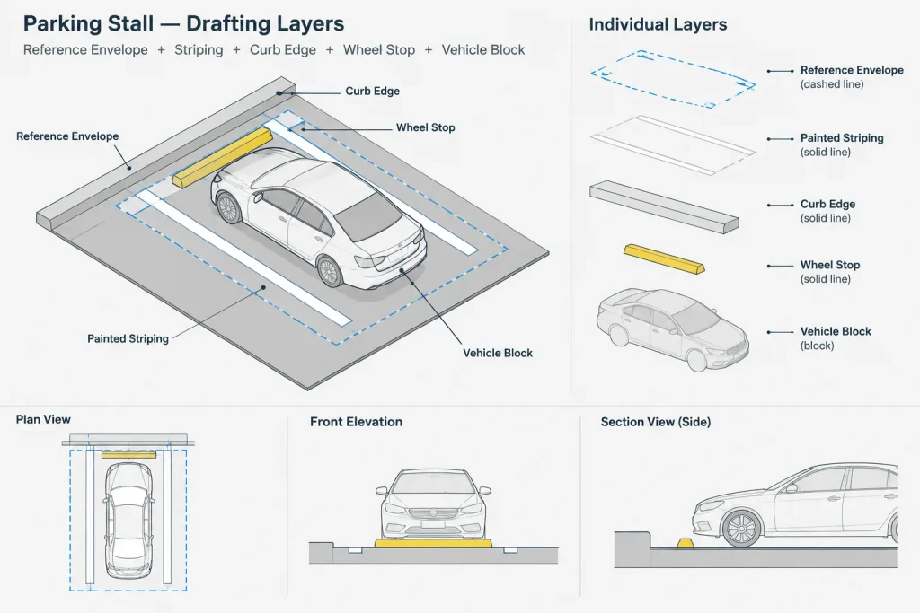
Vehicle blocks are useful for visual review, but they are not automatically valid turning templates. A generic car outline shows occupancy and context; a verified swept-path analysis evaluates movement. Keep those purposes separate.
Resolve row ends, islands, and leftover space
Parking layouts often fail at row ends rather than in the repeated middle bays. Review the transition from the final stall to curbs, islands, sidewalks, walls, gates, and intersecting aisles. Small leftover spaces can create ambiguous striping, difficult maintenance zones, or vehicle overhang conflicts.
Do not force an additional stall into a row merely to improve the count. First check whether the end geometry preserves circulation, visibility, pedestrian movement, landscape needs, and practical curb construction. A cleanly resolved end island may provide more value than a marginal space.
Coordinate accessible parking and pedestrian routes
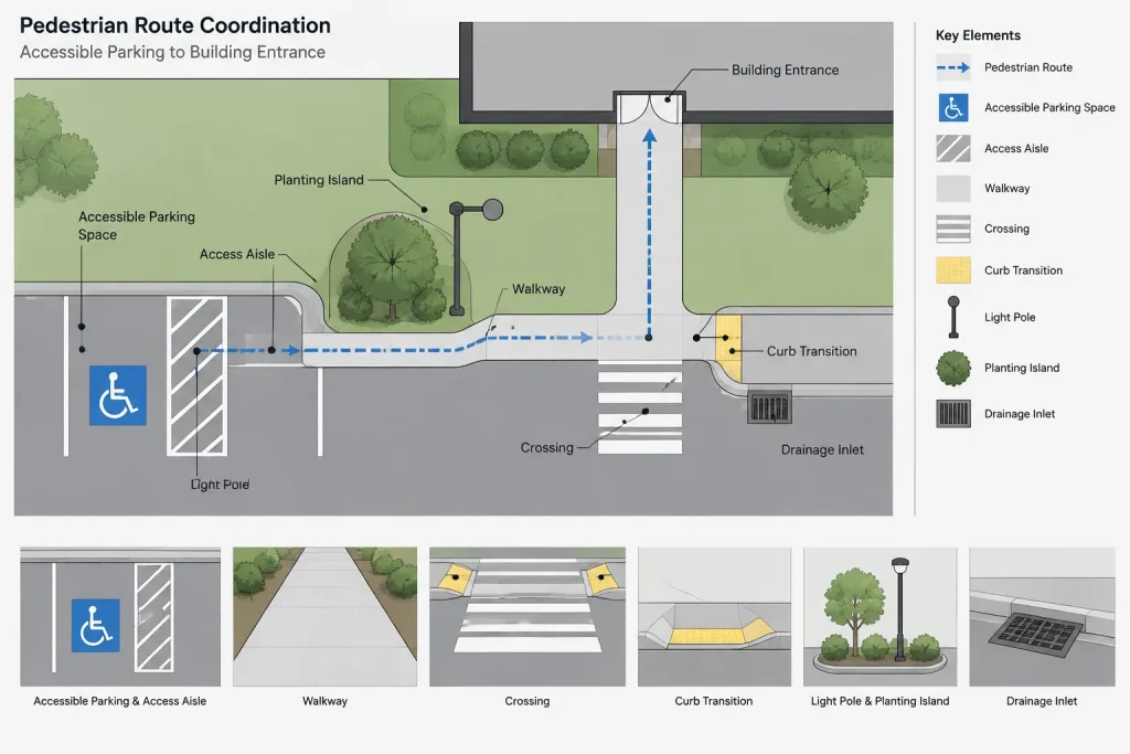
Accessible parking should be developed as part of the entrance and pedestrian strategy, not inserted after the general parking count is complete. Use the project’s verified accessibility criteria to determine quantity, type, distribution, markings, signs, access aisles, slopes, and route requirements.
Trace the complete pedestrian route from each applicable parking area to the destination entrance. Review every transition, including:
- Connections between access aisles and walkways
- Curb ramps and detectable warning locations where required
- Crossings through vehicle aisles
- Changes in level and sloped surfaces
- Bollards, signs, light poles, planters, and drainage structures
- Door swings and entrance maneuvering areas
Use a distinct review polyline or hatch to visualize route continuity. This graphic can be temporary, but it helps reveal interruptions that ordinary striping plans may hide.
Test vehicle movement at critical locations
Not every parking plan needs the same level of movement analysis. At a minimum, inspect entrances, tight turns, dead-end aisles, structured parking transitions, loading areas, refuse collection points, and emergency access routes. Use the correct design vehicle and verified movement data for the specific project.
Keep turning-path graphics on dedicated layers. Show the body path and wheel path distinctly if the analysis method provides both. Check vertical and operational constraints as well as plan clearance; a route that works geometrically may still conflict with gates, overhead elements, steep transitions, or queued vehicles.
Coordinate grading, drainage, and site equipment
Parking striping cannot be finalized independently of grading. Review spot elevations, contour direction, drainage inlets, trench drains, and low points supplied by the civil design. Accessible parking and routes require particular attention because grading changes can affect compliance even when the plan geometry remains unchanged.
Also check that light poles, signs, hydrants, utility cabinets, charging equipment, landscape elements, and protective bollards do not occupy stalls or required circulation areas. Use blocks with realistic plan footprints rather than point symbols when physical clearance matters.
Count and label spaces carefully
Counts should come from controlled geometry rather than visual estimation. Organize stall blocks or closed reference objects so they can be selected, filtered, or extracted consistently. Separate stall categories such as standard, accessible, compact, reserved, charging, or fleet spaces only when those classifications are supported by the project criteria.
Compare the CAD count with the site data table and planning calculations. Then review the drawing visually, because automated counts can include hidden, duplicated, phased, or nonplotting objects. A reliable count combines object-based checking with human review.
Complete a parking plan quality-control review
Before issuing the drawing, run a focused coordination check:
- Confirm that the correct site background and revision are referenced.
- Verify parking geometry against documented project criteria.
- Check circulation direction, arrows, and entrance connections.
- Inspect row ends, islands, curb returns, and dead-end aisles.
- Trace pedestrian and accessible routes from parking to entrances.
- Review turning movements at constrained or operationally important locations.
- Coordinate striping with drainage, utilities, lighting, landscape, and signs.
- Reconcile graphic stall counts with schedules and project calculations.
- Check lineweights, hatches, labels, and symbols in the plotted sheet.
- Remove or freeze temporary guides and test geometry from final views.
A strong parking lot layout in architectural CAD is built through coordinated layers of information. By establishing circulation first, using verified parking modules, separating reference geometry from final striping, and reviewing pedestrian, vehicle, grading, and equipment conflicts together, the drawing becomes easier to revise and more dependable for project coordination.
Manage the parking plan as a coordinated design record
A dependable parking drawing should make it clear which geometry is authoritative, which information comes from consultants, and which objects are temporary design aids. This distinction becomes especially important when survey, civil, landscape, utility, or architectural backgrounds are revised.
Before accepting an updated reference, compare its extents, coordinates, curb geometry, building position, drainage features, and utility locations with the previous version. Avoid moving a consultant reference merely to make it align visually. An unexplained shift may conceal a coordinate, unit, or source-file problem.
Separate design development from issue graphics
Working geometry may include stall envelopes, offset guides, turning checks, pedestrian-route overlays, and alternate curb concepts. Final documentation may show only the approved striping, curbs, symbols, labels, and notes. Keeping these purposes separate reduces visual clutter and helps prevent test objects from appearing on an issued sheet.
Alternatives should also remain identifiable. If several parking concepts are being studied, use separate files, controlled layer states, or another documented project method rather than stacking competing layouts in the same visible drawing area.
Use change-based coordination reviews
A complete review is valuable, but revisions also require attention to what changed. When curbs, entrances, building doors, grading, islands, or site equipment move, identify every dependent element that may need to move with them. Striping can remain graphically neat even after its controlling geometry has become outdated.
- Recheck stall counts after row or island revisions.
- Retrace pedestrian routes when entrances, crossings, or curb ramps change.
- Repeat movement checks when access points or curb returns are modified.
- Review drainage and accessible-route coordination after grading updates.
- Confirm that signs, poles, planting, and utility equipment still have appropriate locations.
Prepare the drawing for interdisciplinary review
A parking plan is easier to coordinate when reviewers can distinguish constructed edges, painted markings, circulation information, and temporary analysis graphics. Use consistent line hierarchy, readable labels, and restrained hatching so conflicts remain visible at the intended plot scale.
When issuing the plan for coordination, record the referenced background revision and identify unresolved assumptions. This helps consultants understand whether a layout is ready for detailed coordination or remains an architectural planning study.
Common drafting problems to investigate
- Misaligned references: Confirm coordinates and units before manually repositioning external files.
- Duplicated striping: Look for overlapping arrays, copied blocks, and remnants from earlier options.
- Broken row logic: Review inconsistent stall orientation, irregular spacing, and poorly resolved end conditions.
- Interrupted routes: Check whether curbs, poles, signs, planting, equipment, or vehicle overhangs obstruct pedestrian movement.
- Misleading vehicle blocks: Do not treat a representative vehicle outline as proof that a turning movement works.
- Count discrepancies: Compare object-based totals with schedules and a visual review of the plotted plan.
The final CAD file should communicate both the proposed layout and the coordination logic behind it. Clear layer separation, controlled references, documented criteria, and repeatable quality checks make later revisions easier to understand and less likely to introduce hidden conflicts.
Parking Lot CAD Layout Questions
Should parking stalls be drawn before drive aisles?
Establish the principal circulation pattern first. Entrances, exits, intersections, service access, and internal vehicle paths usually control where parking rows can fit. Stall modules can then be developed from verified project criteria.
Can a downloaded vehicle block be used for turning analysis?
A generic vehicle block is useful for context and occupancy review, but it does not automatically represent a verified swept path. Movement analysis should use the appropriate design vehicle and an accepted project method.
Why should parking striping and curbs use separate layers?
Curbs are constructed edges, while striping is a marked surface treatment. Separating them makes editing, plotting, counting, and coordination easier and helps prevent painted lines from being confused with physical barriers.
How should accessible parking be added to the plan?
It should be coordinated with entrances, pedestrian routes, grading, signs, markings, and surrounding site elements from the start. Apply the verified accessibility requirements governing the project rather than relying on an unconfirmed standard block.
How can parking spaces be counted reliably in CAD?
Use consistent blocks or closed reference objects that can be selected and filtered by category. Compare the resulting totals with the project schedule, then inspect the drawing for duplicates, hidden objects, phased spaces, and nonplotting geometry.
What should be checked when a civil background is updated?
Review coordinates, curb lines, pavement limits, grading information, drainage structures, utilities, property constraints, and building relationships. Then recheck any parking, route, or movement geometry that depends on the changed information.